Green house intelligent control system is designed to protect the plants from more cool and hot weather and additional control system is included to save power by making fans and lights automatically turn on and off with the help of intelligent control system. In this project intelligent control system is developed using microcontroller and sensors. Green house system have a very important use now a days in agriculture field.Some plants need specific amount of water for their proper growth and more productivity, therefore farmer should provide them proper quantity of water. But its difficult for farmer to get estimation for quantity of moisture in soil. But in this project moisture sensor is used to to provide this facility with intelligent control system.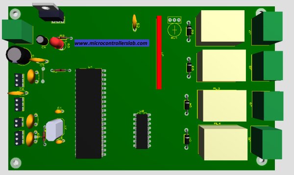
Main functionality of project
Block diagram below shows the main functionality of green house intelligent control system. Four sensors are used to measure different parameters of green house system which includes temperature sensor, light sensor, humidity sensor, moisture sensor. Four relays are used to control four respective loads as given below:
LM35 Temperature sensor :
When temperature become greater than 25 degree, respective relay become energize to operate fan and when temperature become lower than 20 degree relay turn off the fan by getting control signals from microcontroller. PIC16F877A microcontroller analog to digital converter module is used to read temperature value and to operate relay which in turn operate fan. To know more about temperature senor and its working, go through following article :
Digital temperature sensor using pic microcontroller
Light sensor :
Light dependent resistor is used as a light sensor. LDR is kind of variable resistor which resistance changes with the change in light intensity. So LDR resistance is converted into intensity of light by using LDR resistance and intensity of light formula. PIC16F877A microcontroller is used to measure intensity of light. When intensity of light fall under a certain limit, microcontroller provide signal to relay to turn on light and when intensity of light raise upto a certain limit , microcontroller provide signal to relay to turn off fan. So light sensor is used to add automatic light switching functionality in green house system, if you don’t have much money to afford a gardener , then you can use green house intelligent control system to make your green house self operating.
HS1101 Humidity sensor :
Humidity sensor is used to check level of moisture in air Because greater or less humidity level in air can also effect growth of plants. Humidity sensor HS1101 is used to measure level of moisture in air. HS1101 is capactive type humidity sensor, So additional circuit is used to convert change in capacitance of humidity sensor into frequency and frequency is measured with the help of microcontroller. Measured frequency is converted back into humidity using algorithm in microcontroller programming. To know more about humidity sensor and its working, I suggest you to go through following article :
Digital humidity sensor using pic microcontroller
If humisity become grater than a specified limit, microcontroller give signal to respective realy to turn on sprinter which is used to maintain humidity level in air and when humidity level come back to normal limit, microcontroller give signal to respective relay to turn off sprinter.
Moisture sensor :
Moisture sensor is used to measure level in soil. A wire strip is used to measure moisture of soil. Wire strip have a specific resistance at specific moisture, but when moisture increases, resistance of wire strip start decreasing and similarly when moisture decreases, resistance become hire. PIC16F877A used to measure moisture level and to turn on and off water pump with the help of relay.
Simulation :
For simulation purpose I have connected four LED’s instead of real load to check project working and code. LCD is used to display digital values of temperature, light , humidity and moisture. LCD also display the status of devices either they are on or off. As shown in figure below.
Simulation diagram with status of devices :
In simulation I have used variable resistor for wire strip and pulse having different frequencies for humidity sensor.
In above circuit diagrams :
L : for light
S : Sprint
F : for fan
P : for pump
T : for temperature
H : for humidity
M : for moisture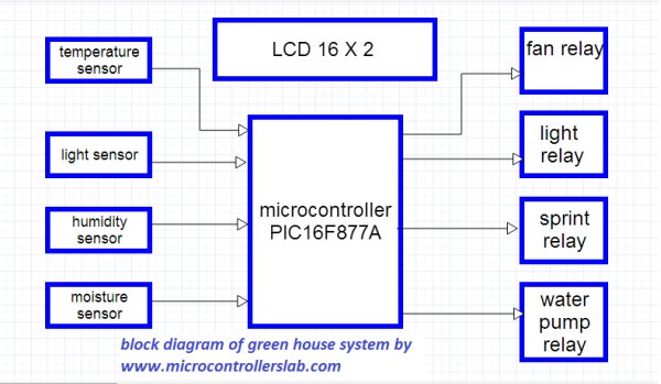
Complete circuit diagram :
Complete circuit diagrams of green house intelligent control system and sensors are shown below :
In above schematic of green house system, blue arrow shows connection for senors and back arrow shows relay and lcd connection point.
For more detail: Green house intelligent control system
Current Project / Post can also be found using:
- how to make working project of temperature measurement and control system
- ic based metering for temperature measurements rs232
The post Green house intelligent control system appeared first on PIC Microcontroller.