OBJECTIVE:
- Temperature measurement
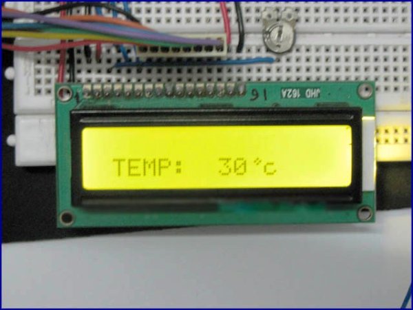
- Digital display of temperature
- used of microcontroller to measure temperature
- used of microcontroller to Display temperature value on LCD (liquid crystal display)
Components:
There are many temperature sensors available in market. But LM35 temperature sensor is used in this project. It is cheapest in price and one can easily find it in market. There are many other advantages of LM35 like:
- It is more efficient than thermistor
- It is made up of integrated circuit hence no chance of damaging to internal circuitry.
- It draws current only in micro Amperes.
Only 5 volt power supply is required for LM35 and there is no need of extra circuitry to operate it. PIC16F877A microcontroller is used to read temperature value. 16X2 LCD is used to display temperature value on LCD. Code of this project written in Mikro C compiler.
Implementation:
LM35 temperature sensor converts temperature into its proportional analog voltage value. LM35 is three terminal device.Pin number one and three are for 5-volt voltage supply. Pin two is analog voltage output with respect to temperature value.Relation between measured temperature and analog output voltage is:
1oC = 10m volt
Hence for every 1 degree increase in temperature there will be a increment of 10m volt in output voltage of LM35 sensor. PIC16F877A microcontroller is used to measure analog voltage value. PIC16F877A microcontroller built in ADC (analog to digital converter) is used to measure analog voltage. PIC16F877A PORTA have seven built in ADC channels. So one can interface up to seven sensors with this microcontroller very easily.I will post a project on green house system.In green house system project I have used four ADC channels to measure temperature , light, humidity and moisture. Coming back to our digital thermometer, ADC has been used to read analog voltage. After reading ADC value, using voltage and temperature relationship voltage is converted back into temperature. A conversion factor is used to convert voltage back into temperature. All these conversion has been done through programming. LCD is connected to PORTB of PIC16F877A microcontroller. I will discuss it in programming part. LCD is used to display temperature value.
Circuit diagram:
Proteus is used for simulation. Following is a circuit diagram of Digital temperature sensor:

temperature sensor circuit diagram
As shown in above figure both temperature sensor and LCD is displaying same values of temperature. To ensure protection of LM35 and microcontroller you can connect 80k ohm resistor parallel to output of temperature sensor.
For more detail: Temperature sensor using PIC16F877A microcontroller
The post Temperature sensor using PIC16F877A microcontroller appeared first on PIC Microcontroller.