Quantcast
Channel: Temperature Measurement Projects - PIC Microcontroller
Viewing all 121 articles
Browse latest View live

DCF77 clock-thermostat using PIC16F648A

$
0
0

Always at the right time your house on temperature

This project make use of a PIC16F648(A) and a DCF77 receiver from Conrad (Orderno. 64 11 38)
With DCF77 runs the clock from the thermostat always on the right time.
Synchronizing isn’t necessary anymore.

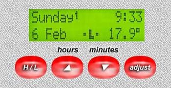
The temperaturesensor is a DS1820 or DS18B20 and on a HD44780 (or compatible) 2×16 LC-Display becomes day, date, time, temperature (with 0.1°C precision) and an indication which temperature adjustment (economy- or comfort temperature) is active.

clock-thermostat

For each day there are 4 ON/OFF times to program, ON means here switch to the comfort temperature and OFF to the economy temperature.
A handy option is for people who work at different times (shift work) because it is possible to program the clock with a 2-weeks scheme.

Control
Controlling the clock-thermostat is very simple, buttons and commands to synchronize the clock are left away because of DCF77.
There are set 2 temperatures, a Low economy- and a High comfort temperature.
Only 4 buttons to control everything.

Button 1 switches manual from L (economy) to H (comfort) temperature and vice versa.
Button 2 sets the comfort temperature higher per 0.5°C.
Button 3 sets the comfort temperature lower per 0.5°C.
Button 4 must pushed for 2 seconds to go to the “timer adjustmentsmenu” (see further).

The economy temperature, (when nobody is at home or at night) stays normally always at the same temperature (±16.0°C).
Set this temperature eventually higher by pushing button 1 and button 2 at the same time or lower by pushing button 1 with button 3, but normally this is never necessary.


When switching the power on, the PIC let see an intro for a few seconds, when the paper manual is lost, then you can see where to find information about this clock thermostat.

After that shows the LCD the version number from the PIC program and in what mode the week-timers are.

Then the PIC waits till it get a signal from the DCF77 module (receiver).

When searching does take more than 45 seconds, the message “No DCF signal” follows.
The PIC stays searching until it have a decent timesignal reception.
The manual control from the heating is working when there is no DCF signal, only the timers don’t work.


For more detail: DCF77 clock-thermostat using PIC16F648A

Current Project / Post can also be found using:

  • DCF77clock-thermostatusingPIC16F648A

The post DCF77 clock-thermostat using PIC16F648A appeared first on PIC Microcontroller.

Digital thermometer with auto saving log file in excel by Pic microcontroller

$
0
0

Digital thermometer with auto saving log file in excel by Pic microcontroller is vary advance, useful and realistic project. The implementation filed of this project is wide. Now a day’s atmospheric prediction saves lots of life. And for getting wright prediction we have to analysis lots of recorded data. By using this project it can be easily serve the purpose.

Project description:

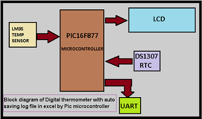
To know the project description you should know that how it works? In this project “Digital thermometer with auto saving log file in excel by Pic microcontroller “we use LM34 IC as a temperature sensor which sense the atmospheric temperature and send the analog value of it. Now we know microcontroller can only process digital value so we convert the analog value which sends by LM34, by inbuilt ADC unit of PIC16f877. After converting the reference temperature value microcontroller process it with some mathematical formula to convert the reference value in Centigrade scale. We interface DS1307 IC for getting the time and calendar in real time mode. To know the details step by step tutorial on “how to interface DS1307 with PIC16f877 microcontroller?” you may follow my old post Interfacing DS1307 Real time clock with PIC16f877. Now big question is how to create log file in excel and save it to PC? For now that you have to see the bellow video where you find the step by step process on how using windows HyperTerminal software, we can receive data via comport (serial communication) and capture the data in CSV format. So for saving the data in CSV format we have to send comma separated data with exact format via UART from PIC16F877 microcontroller.

Digital thermometer with auto saving log file in excel by Pic microcontroller

CSV Data format and Creation inside PIC:

It is a major thing we have to do for sending data in CSV format. As we know the name CSV means comma separated values so we have to send every data separated by comma. And as per Excel for changing column we have to press Tab Key and for change Row we have to press Enter Key. To make our format accordingly our plan we have to send data followd by comma and others key. In this project, we save the data at three column for temperature, time and date see in fig. For that we use code (In Mikroc for Pic) given bellow.

Digital thermometer with auto saving log file in excel by Pic microcontroller schematic

UART1_Write_text(tem);       // send data (temperature) via UART

UART1_Write(0x2c);             //” comma

UART1_Write(0x09);             //  Tab

UART1_Write_text(time);      // send data (time) via UART

UART1_Write(0x2c);            //” comma

UART1_Write(0x09);            // Tab

UART1_Write_text(date);     // send data (Date) via UART

UART1_Write(0x2c);            //” comma

UART1_Write(0x0D);     // Enter


For more detail: Digital thermometer with auto saving log file in excel by Pic microcontroller

Current Project / Post can also be found using:

  • use of electronic thermometer in home fan

The post Digital thermometer with auto saving log file in excel by Pic microcontroller appeared first on PIC Microcontroller.
About the Temperature Sensor using pic microcontoller

$
0
0

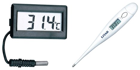
Temperature sensors are used in a wide range of electronic devices, including digital thermometers, home thermostats, ovens, and refrigerators. Figure 1 shows two devices with temperature sensors.

Figure 1. Devices with temperature sensors.

The temperature sensor provided in your kit is a precision analog sensor, whose voltage output is linearly proportional to the temperature. Configured as described here, the sensor has an operating range of about 0°C to +150°C.

About the Temperature SensorConnecting the Temperature Sensor

The temperature sensor is a three-pin integrated circuit. When the device’s flat side is facing towards you, the three pins are labeled 1, 2, and 3, from left to right, as shown in Figure 2.

Depending on your kit, you may have either an LM35 temperature sensor or an LM335 temperature sensor. You can identify your sensor by reading the text on the flat face of the device, as shown in Figure 3. The two sensors are wired slightly differently on the breadboard and produce different analog outputs, so it is critical to identify which type you have before moving ahead.

Figure 3. LM35 (left) and LM335 (right).
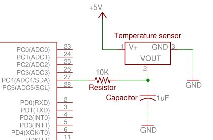
If you have the LM35, connect the temperature sensor as shown in Figure 4. Pin 1 is connected to power, and pin 3 is connected to ground. Pin 2 connects to ground through a 1.0 uF capacitor, and to Port C4 (pin 27) on the microcontroller through a 10K Ohm resistor.
If you have the LM335, connect the temperature sensor as shown in Figure 5. Pin 1 is inserted into the breadboard but not connected to anything. Pin 3 is connected to ground. Pin 2 connects to power through a 1K ohm resistor, and to Port C4 (pin 27) on the microcontroller.

Reading and Plotting Temperature Data

Using MATLAB, it is possible to plot data gathered from the ATmega microcontroller. Using the ms.adc_read command, you can have MATLAB gather data from the temperature sensor and display the temperature over time as an x-y graph.
About the Temperature Sensor1. Send command prompt instructions to read the ADC value from the temperature sensor:

>> data=ms.adc_read(4); %Set data equal to temperature value
>> data %Display the current value for the temperature

2. Write a program in the editor window to plot the data from the temperature sensor:

if exist(‘ms’)   %Remove previous connections
delete(ms)
endms=msci.breadboardkit(‘COM#’)   %Connect to com port
msdefines   %Ensure you have ms objects

for i=1:60   %Start a loop with 60 cycles
pause(1)   %Pause for 1 second

data=ms.adc_read(4)   %Read the analog value
plot(i, data, ‘rs’)   %Plot the iteration and the value
drawnow   %Draw all points plotted so far
hold on   %Keep the same graph on the screen
axis([0 60 0 40])   %Set the x and y axis extentsend

xlabel(‘Time (s)’);   %Label the x axis as Time
ylabel(‘Analog Value’);   %Label the y axis as Analog Value

delete(ms)

The post About the Temperature Sensor using pic microcontoller appeared first on PIC Microcontroller.
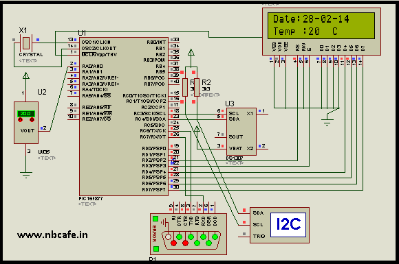
Humidity and temperature measurements with Sensirion’s SHT1x/SHT7x sensors (Part 1) using pic microcontoller

$
0
0
Temperature and relative humidity are two very important ambient parameters that are directly related to human comfort. Sometimes, you may be able to bear higher temperatures, if there is a lower relative humidity, such as in hot and dry desert-like environment. However, being in a humid place with not very high temperature may make you feel like melting. This is because if there is high relative humidity, sweat from our body will evaporate less into the air and we feel much hotter than the actual temperature. Humidifiers and dehumidifiers help to keep indoor humidity at a comfortable level. Today we will discuss about Sensirion’s SHT series of digital sensors, more specifically SHT11 and SHT75, which are capable of measuring both temperature and relative humidity and provide fully calibrated digital outputs. We will interface both the sensors to PIC18F2550 microcontroller and compare the two sets of  measurements to see the consistency between the two sensors. This tutorial is divided into two parts. The first part will cover all the details regarding the sensors, including their specification, interface, and communication protocol. The second part will be more focussed on the circuit diagram, implementation of the communication protocol with PICMicro, and the results.
Humidity and temperature measurements with Sensirion’s SHT1x SHT7x sensors (Part 1)Theory

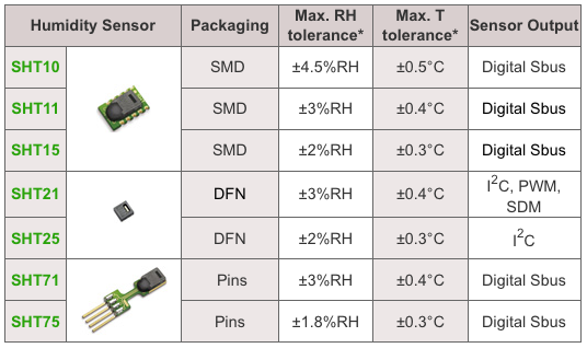
Sensirion offers multiple SHT series of digital sensors for measuring both relative humidity and temperature. The temperature is measured using a band-gap sensor, whereas the humidity sensor is capacitive; which means the presence of moisture in air changes the dielectric constant of the material in between the two plates of a parallel-plate capacitor, and hence varies the capacitance. The required signal conditioning, analog-to-digital conversion, and digital interface circuitries are all integrated onto the sensor chip. The various SHT series sensors have different levels of accuracy for humidity and temperature measurements, as described below.

SHT1x are available in surface mount type whereas SHT7x are supplied with four pins which allows easy connection. The SHT11 and SHT75 sensors both provide fully calibrated digital outputs that can be read through a two-wire (SDA for data and SCK for clock) serial interface which looks like I2C but actually it is not compatible with I2C. An external pull-up resistor is required to pull the signal high on the SDA line. However, the SCK line could be driven without any pull-up resistor. The signaling detail of the serial bus is described in the datasheet, which we will implement for PIC18F2550 microcontroller using mikroC pro for PIC compiler. The operating range of both the sensors is 0 to 100% for relative humidity, and -40.0 to 123.8 °C for temperature. The sensor consumes 3 mW power during measurement, and 5 ?W, while in sleep mode.

The SHT11 module that I have got is from mikroElektronika. The sensor (SMD) is soldered on a tiny proto board with all the four pins accessible through a standard 0.1 inch spacing male header. The board comes with pull-up resistors connected to both SDA and SCK lines. One concern in this type of arrangement is the heat dissipated by the pull-up resistors could affect the measurements if the resistors and the sensor are close in the board. We will discuss about this issue later too. The SHT75 module from Sensirion, however, does not include any pull-up resistor for SDA line and therefore must be included externally.

Brief description of SHT1x/7x sensors

Please read the datasheets for SHT1x and SHT7x for detail information about these sensors. I am only providing a brief summary here.

SHT11 and SHT75 are functionally same with SHT75 being more accurate (±1.8% vs ±3%) in measuring relative humidity. Both the sensors can operate from 2.4-5.5 V supply voltage, however the datasheet recommends to use 3.3V for highest accuracy. The default measurement resolution is 14-bit for temperature and 12-bit for relative humidity, which can be reduced to 12- and 8-bit respectively by changing the bit settings of the Status Register (discussed later) inside the sensor chip. We will be using the default resolution settings for measurements.

Humidity and temperature measurements with Sensirion’s SHT1x SHT7x sensors (Part 1)SCK is the clock line that is used to synchronize the communication between the micrcontroller and the sensor. It is an input only pin on the sensor’s side and therefore the microcontroller should be responsible to generate the clock signal. DATA or SDA is a bidirectional data transfer pin for sending data in and out of the sensor. The sensor should receive a conversion command from the microcontroller in order to start measuring temperature or relative humidity. The measurement commands for relative humidity and temperature are 00000101 (05H) and 0000011 (03H), respectively [The first three most-significant bits are actually the address bits, which are always zero for SHT1x and SHT7x sensors, and the remaining 5 bits are the command bits]. Prior to sending a command, a Transmission Start sequence must be issued by the microcontroller which consists of a lowering of the DATA line while SCK is high, followed by a low pulse on SCK and raising the DATA line high again, while the SCK is already high.


The post Humidity and temperature measurements with Sensirion’s SHT1x/SHT7x sensors (Part 1) using pic microcontoller appeared first on PIC Microcontroller.
Digital Thermometer using PIC Microcontroller and LM35 Temperature Sensor

$
0
0

A Digital Thermometer can be easily constructed using a PIC Microcontroller and LM35 Temperature Sensor. LM35 series is a low cost and precision Integrated Circuit Temperature Sensor whose output voltage is proportional to Centigrade temperature scale. Thus LM35 has an advantage over other temperature sensors calibrated in Kelvin as the users don’t require subtraction of large constant voltage to obtain the required Centigrade temperature.

Digital Thermometer using PIC Microcontroller and LM35 Temperature SensorIt doesn’t requires any external calibration. It is produced by National Semiconductor and can operate over a -55 °C to 150 °C temperature range. Its output is linearly proportional to Centigrade Temperature Scale and it output changes by 10 mV per °C.

The LM35 Temperature Sensor has Zero offset voltage, which means that the Output = 0V,  at 0 °C. Thus for the maximum temperature value (150 °C), the maximum output voltage of the sensor would be 150 * 10 mV = 1.5V.  If we use the supply voltage (5V) as the Vref+ for Analog to Digital Conversion (ADC) the resolution will be poor as the input voltage will goes only up to 1.5V and the power supply voltage variations may affects ADC output. So it is better to use a stable low voltage above 1.5 as Vref+. We should supply Negative voltage instead of GND to LM35 for measuring negative Temperatures.

Digital Thermometer using PIC Microcontroller and LM35 Temperature SensorThis article only covers the basic working of Digital Thermometer using PIC Microcontroller and LM35, and uses 5V as Vref+. If you want more accurate results it is better to select Vref+ above 2.2V. I suggest you to use  MCP1525 IC manufactured by Microchip, which will provide precise output voltage 2.5.


For more detail: Digital Thermometer using PIC Microcontroller and LM35 Temperature Sensor

The post Digital Thermometer using PIC Microcontroller and LM35 Temperature Sensor appeared first on PIC Microcontroller.
DS18S20 Dual Temperature Meter using pic microcontroller

$
0
0
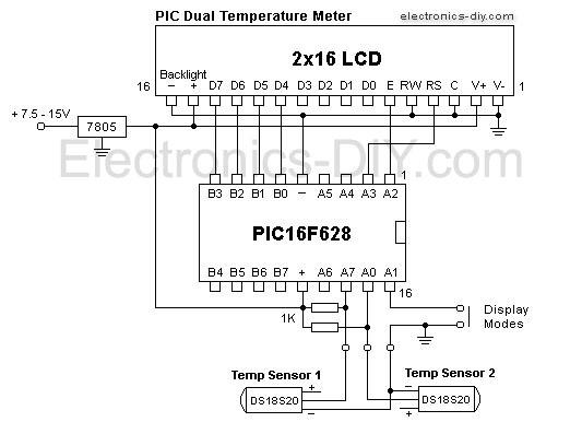
 DS18S20 Dual Temperature Meter Component List:
1x 2×16 LCD with Backlight
1x 16×1 LCD Female Header Connector
1x 16×1 LCD Male Header Connector
1x Programmed PIC16F628
2x DS18S20 1-Wire Digital Temperature Sensor
1x 100nF Capacitor
1x 10K Pot (LCD Contrast)
1x 10K Resistor
2x 1K Resistor
1x 10 Resistor
1x LM7805 Voltage Regulator
1x Tactile Switch (Display Modes)
1x 2-PIN Male Header Connector
1x 4-PIN Male Header Connector
  Technical Specifications:
Temperature Measurement:
-55 to 125°C (-67 to 257°F)
Accuracy: 0.5 °C / 1 °F
Supply Voltage: 7.5 – 15V
Power Consumption: 8mA (when LCD backlight is turned off)


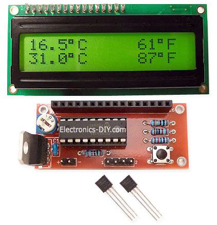
DS18S20 Dual Temperature MeterDS18S20 Dual Temperature Meter

This is a simple to build DS18S20 dual temperature meter that allows to measure temperature in two different locations at the same time. The meter is built with very few components thanks to the use of PIC16F628 microcontroller and 2×16 character LCD display. It is like a small computer that can be customizable by upgrading its hex firmware.

DS18S20 dual temperature meter uses two very exciting DS18S20 digital temperature sensors that come in convenient TO92 package. Unlike regular sensors where temperature readings are passed as varying voltage, DS18S20 passes temperature information in a digital format as data. This brings many new possibilities and enables to pass temperature information over much longer distances just over a two wire cable. With this capability temperature can be measured in different locations at the same time away from the main circuit board. With regular temperature sensors that rely on the voltage cables must be as short as possible because longer wire lengths introduce stray resistance and bring unreliable readings.

Another great feature of DS18S20 sensor is that it doesn’t require any calibration at all, while providing 100% accuracy out of the box. That means that you just plug it in and there’s no need spending time recalibrating temperature readings. This is all due thanks to the nature of sending information in a digital format. In fact DS18S20 is just like a computer connected to the network that has a unique serial number identifier similar to an IP address.

DS18S20 Dual Temperature MeterMultiple DS18S20 sensors can send information simultaneously, even over the same two wire bus cable. The two wires provide 3-5V voltage supply to the sensors and they are also used to pass data in two different directions. If wires are very long so that voltage on DS18S20 sensors drops below 3V external 5V voltage supply can be used with 1K resistor to power the sensors.

Once PIC microcontroller receives temperature information it converts it into both Celsius and Fahrenheit values so that they can be displayed on LCD display. DS18S20 dual temperature meter is capable of measuring temperatures from -55 to 125 °C degrees Celsius (-67 to 257 °F Fahrenheit) with 0.5 °C / 1 °F accuracy. If you just need to measure temperature in one location you may just use one DS18S20 sensor and PIC16F628 microcontroller will use just one sensor.

For more detail: DS18S20 Dual Temperature Meter

The post DS18S20 Dual Temperature Meter using pic microcontroller appeared first on PIC Microcontroller.
12F675 Tutorial 5 : A Temperature data logger using PIC EEPROM. using pic microcontroller

$
0
0

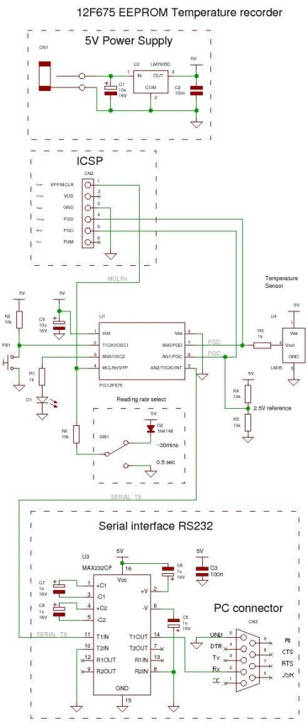
EEPROM is useful for storing long term data such as data logger information and this PIC microcontroller EEPROM project saves the temperature from an LM35DZ IC to the PIC’s internal long term data storage area.  The project follows on from the last project using the virtually the same hardware.
It stores temperature readings internally at regular intervals until full and after this it turns on the LED. The LED is really just for showing that something is happening and in a real data logger you would not use it.
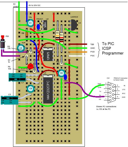
12F675 Tutorial 5 A Temperature  data logger using PIC EEPROM.Jump to Solderless breadboard.
Jump to Circuit Diagram.
Jump to Software.

Note: This project is not optimized for power consumption so the best way to use it is powered from a power block.  The current consumed is about 13mA (LED off) 16mA (LED on at end). If you want to use a battery use a rechargeable PP3 and do not attach the LED.

The 12F675 may not the best PIC microcontroller to use for low power data logging and a better choice would be the 16F88 as it can change its internal oscillator on the fly going into slow (current saving) mode.  But you could use the 12F675 with a slow external 32kHz crystal. 

At every ADC reading the LED is flashed briefly and when you select a 500ms reading interval you can see the readings being taken.  When 64 readings are accumulated the LED is lit permanently – showing that the data store is full.


Note: For this chip you only get to store 64 results as you need to store an unsigned integer for every ADC result and this takes 2 bytes so 128 Bytes/2  = 64 results.
You can hit the button at any time and the contents of the EEPROM will be read from the internal EEPROM and transmitted to the PC via the serial port.

To erase the internal EEPROM hold the button and cycle the power – this flashes the led 6 times indicating erase (normal startup flashes the LED 3 times).

Solderless breadboard

The solderless breadboard and circuit diagram are nearly the same as used in the previous project so if you have already built it you don’t need to do any more.  Just add the blue wire, D2 and R6.

12F675 Tutorial 5 A Temperature  data logger using PIC EEPROM.

Circuit diagram

Note that the switch shown below is just a blue wire above. Either leave the  blue wire where it is to hold the input, at pin 4, high or move the top of the blue wire to ground (0V – green wires at top left – on the left of the solderless breadboard) to set GP3 (pin 4) low.

Note: The diode stops the programming voltage conflicting with the 5V power supply – reversed biased when the high programming voltage is present.


For more detail: 12F675 Tutorial 5 : A Temperature  data logger using PIC EEPROM.

The post 12F675 Tutorial 5 : A Temperature data logger using PIC EEPROM. using pic microcontroller appeared first on PIC Microcontroller.

Intelligent Fan Controller. Part 1 – Schematic using pic microcontoller

$
0
0

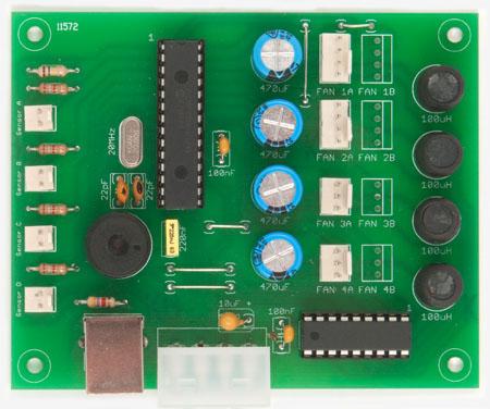
he Intelligent Fan Controller is designed to control the noise generated by the fans inside your computer. It does this by varying their speed based on temperatures measured inside the case. When it is cool the fans will run slowly and they will only speed up when needed… when your computer is running hot.

Anyone with a noisy computer, especially a Media Centre system in the lounge room, will benefit from this project. After installing this device, my computer is now so quiet that I can hardly tell that it is running – and that is a blessed relief.

Intelligent Fan Controller. Part 1 - SchematicThe main features are:

  • Configurable speed control based on temperatures measured inside your computer
  • Control up to eight fans and measure up to four temperatures
  • USB interface and Windows software for setup and monitoring
  • It will run independently without the Windows software (once it has been configured)
  • Cheap – The cost for all the parts is about $48

The Intelligent Fan Controller was featured in the July 2010 issue Silicon Chip magazine. Altronics are selling a full kit of parts for the Intelligent Fan Controller (Part nbr K6120). This is an easy way to get everything that you need to build the controller including a pre programmed microcontroller and a printed copy of the full magazine article – ideal if you are not an electronics expert and just want to silence your computer.

The Circuit

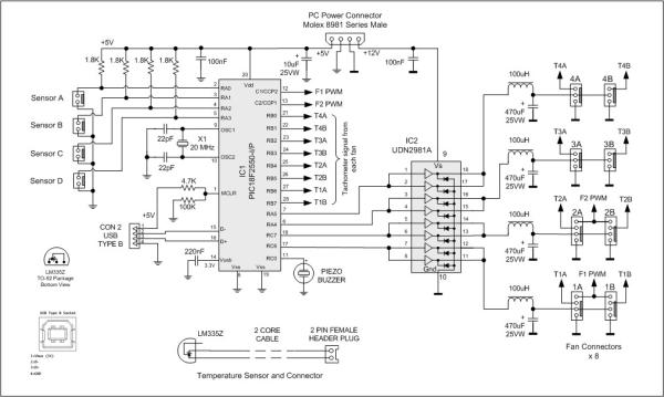
The circuit below shows just how simple the fan controller is. In the centre is a Microchip PIC18F2550 microcontroller, it reads the voltage from the temperature sensors LM335 (on the left) and controls the voltage converters on the right. It is by varying the voltage output of the converters that the microcontroller can control the speed of the fans.

Intelligent Fan Controller. Part 1 - SchematicEach voltage converter is implemented as a buck converter. The microcontroller generates a string of pulses on each output for each buck converter and, by varying the pulse width, the microcontroller can vary the output voltage. In this implementation the pulse rate is 2.5KHz and the pulse width varies between zero and 170µS to give an output between zero and 12V. Note that IC2 UDN2981A does double duty as a fast switch and a diode – both required in the buck converter design. For $2.20 this is a handy little chip.


For more detail: Intelligent Fan Controller. Part 1 – Schematic

Current Project / Post can also be found using:

  • digital thermometer with auto saving log file in excel by Pic microcontroller

The post Intelligent Fan Controller. Part 1 – Schematic using pic microcontoller appeared first on PIC Microcontroller.

Water Level Indicator and Controller using PIC Microcontroller

$
0
0

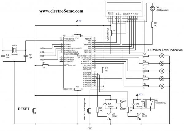
Here is a simple, versatile project which indicates the level of water and automatically controls it by using PIC Microcontroller. The Water Level Sensing Section senses the level of water in the tank and sends it (wireless) to the Receiver Section. Receiver Section is connected to the Controlling Section, which process the received information and produces visual, sound indications and controls the operation of the motor whenever required. The project is divide into 4 sections.

Water Level Indicator and Controller using PIC Microcontroller

1. Power Supply Section

Power Supply section provides required supply for Receiver and Controlling modules. Receiver module requires +5V power supply. Controller module requires +5v and +12v supply. Circuit Diagram:

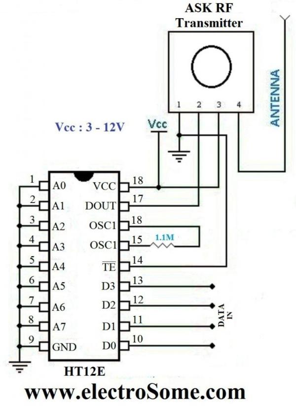
Level Sensor module is made of with HT12E encoder and ASK (Amplitude Shift Keying) RF transmitter. This circuit can be drive using 9V battery. For more details about this transmitter, please read the article Wireless RF Transmitter and Receiver using ASK RF Module. This circuit is placed near the Water Tank and connected to the tank as show in the figure below.

Receiver Module is made of with HT12D decoder and ASK RF receiver. The data transmitted by the Sensor module is received by this module and is given to the Controlling Module. For more details about this receiver, please read the article Wireless RF Transmitter and Receiver using ASK RF Module.

Water Level Indicator and Controller using PIC MicrocontrollerThe soul of the Controlling Section is PIC16F877A. It process the data given by the Receiver Section. LCD Display, LED Indications and Motor status are updated according to the data. You can download the hex file and mikroC Source Code at the bottom of this article.


For more detail: Water Level Indicator and Controller using PIC Microcontroller

Current Project / Post can also be found using:

  • advantage of automatic temperature control based on PIC microcontroller
  • pic microcontroller based temperature controller project
  • project of water level indicator using pic16F877a
  • temperature measurement project

The post Water Level Indicator and Controller using PIC Microcontroller appeared first on PIC Microcontroller.
Temperature Recorder using PIC12F683 microcontroller

$
0
0

Description

This project uses a MicrochipPIC microcontroller, a serial EEPROM and a thermistor to create a temperature recorder.

Temperature Recorder

Performance

The temperature is measured and stored at user programmable intervals; this can be from 1 second to 256 seconds. The time interval is set by programming it and the start time into the EEPROM.

Most of the time the PIC will be asleep and the EEPROM IC is inactive. This gives a very low current consumption of approximately 50 uA or about 1 mAh per day.

The EEPROM used is 32kBytes which can store up to 32,000 measurements. This could be one measurement every 30 seconds for 11 days for example.

The combination of thermistor and analogue circuit gives a range of between about -40 °C and +100 °C although the linear range is between about -10 °C and +40 °C.

Complete Unit

In this picture the temperature recorder can be seen with the external thermistor plugged in. The connector on the end contains power, I2C clock and data and analogue input.

The overall size of the complete unit is 40 mm long, 26 mm wide and 16 mm tall.

In this picture the temperature recorder is connected to a battery pack with 4xAAA batteries. This gives a good indication of the size and shows that I need a much smaller set of batteries.

PCB (version 1)

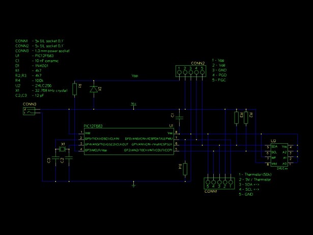
The first version of the circuit is built on stripboard with DIL packaged ICs and conventional through-hole passive components.

The PIC microcontroller is to the left of centre on the PCB with the EEPROM IC mounted vertically to save space on the right of centre.

The external connectors are the 1.3mm power socket on the bottom left and the 5 pin SIL socket on the right.

Schematic Temperature Recorder

The other components are the ICSP socket with resistor and diode at the top left, crystal oscillator and two capacitors on the left of the PIC, the two I2C pull-up resistors next to the EEPROM and the resistor for the thermistor potential divider at the top right.


For more detail: Temperature Recorder using PIC12F683 microcontroller

The post Temperature Recorder using PIC12F683 microcontroller appeared first on PIC Microcontroller.
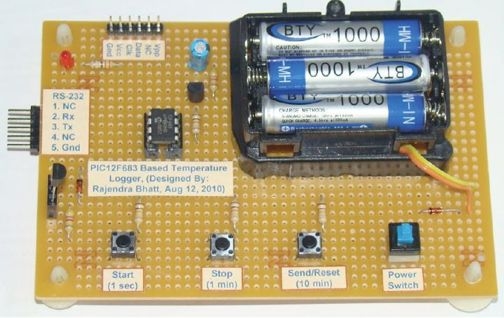
Simplest Temperature Data Logger using PIC12F683

$
0
0

Introduction
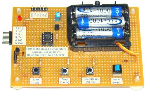
There are varieties of digital temperature logger projects available online based on different microcontrollers. The one I am going to talk about is based on a Microchip’s 8-pin microcontroller, PIC12F683. It reads temperature values from a DS1820 digital sensor and stores in its internal EEPROM. PIC12F683 has 256 bytes of internal EEPROM and we are going to store the temperature values in 8-bit format. This means only the eight most significant bits of temperature data from DS1820 will be read and as such the temperature resolution will be of 1 degree C.

Logger

My temperature logger has following features:

  • Reads temperature from a DS1820 sensor and stores in the internal EEPROM locations.
  • Can store up to 254 temperature values. EEPROM location 0 is used to store the sampling interval, and location 1 is used to store the number of records.
  • Three sampling interval options: 1 sec, 1 min, and 10 min. This can be selected during powering up.
  • Start and Stop buttons for control operations.
  • The recorded temperature values can be sent to PC through a serial port. A separate Send button is available to initiate data transfer.
  • A LED to indicate various ongoing operations.
  • Reset button to clear all previous records.


Circuit Design
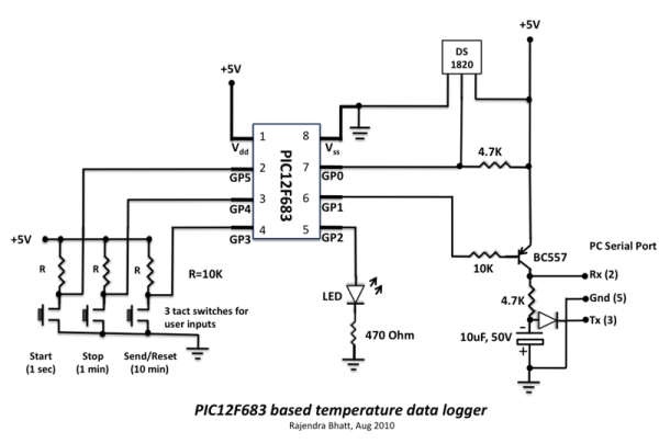
PIC12F683 has 6 I/O pins, out of which one (GP3, pin 4) is I/P only pin. Here is how we are going to assign the port pins.
The six I/O pins of PIC12F683 are assigned as follows:
1. GP0 (Pin 7, I/P): This pin will be used to read the temperature value from DS1820 sensor.
2. GP1 (Pin 6, O/P): This will be used for serial data transfer to a PC.
3. GP2 (Pin 5, O/P): LED output pin.
4. GP3 (Pin 4, I/P): Send (tactile switch)
5. GP4 (Pin 3, I/P): Stop (tactile switch)
6. GP5 (Pin 2, I/P): Start (tactile switch)

The post Simplest Temperature Data Logger using PIC12F683 appeared first on PIC Microcontroller.
A DIY indoor thermometer plus hygrometer using PIC16F688

$
0
0

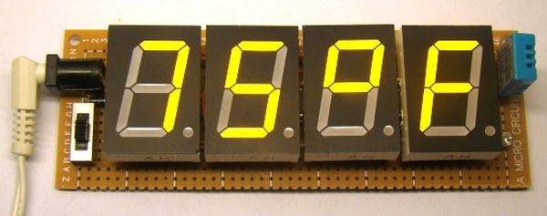
This project is about building a microcontroller-based digital room thermometer plus hygrometer that displays temperature and relative humidity on 4 large (1 inch) seven segment LED displays which adjust their brightness level according to the surrounding illumination. It consists of a closed loop system that continuously assesses ambient light condition using an inexpensive light-dependent resistor (LDR) and uses that information to adjust the brightness of the display. An inexpensive DHT11 sensor is used to measure temperature and relative humidity. The microcontroller used in this project is PIC16F688, and it runs at 4 MHz clock generated from its internal source. A separate display driver chip (MAX7219) is used to control and refresh the display data on the seven segment LEDs.

TRH Meter Prototype OP2

Why do we need adaptive brightness control?

Auto-adjusting the brightness of the seven segment LED displays not only saves power but also enhances the readability in all ambient lighting conditions.

Many smartphones, HDTVs, PDAs, tablets, and computer screens now come with this feature. It basically dims the display in a dark environment and is still readable and eye-soothing. Similarly, when the ambient light level goes up, it brightens the display to enhance the readability. This project displays indoor temperature and relative humidity on large 1 inch seven segment LEDs that automatically adjust the brightness to be in balance with the light condition in the room. So, if you put this meter in your bedroom, you won’t have to worry about turning it off during nighttime. It will automatically dim low enough to not to disturb your sleep, while maintaining the readability.

Circuit diagram 

To make it easy to explain, I have divided the complete circuit diagram into 3 parts: Power supply unit, Microcontroller and sensor unit, and Display driver unit.

The power supply unit consists of a LM7805 regulator IC to derive regulated +5V power supply from a 9-15V DC wall adapter. The complete power supply unit circuit diagram is shown below. LED1 is a power-on indicator LED.

The following circuit diagram shows connections of the DHT11 sensor and the photoresistor (also called light dependent resistor or LDR) to the PIC16F688 microcontroller. DHT11 is a low cost digital sensor for measuring temperature from 0-50 °C with an accuracy of ±2°C and relative humidity ranging from 20-95% with an accuracy of  ±5%. The sensor provides fully calibrated digital outputs and has got its own proprietary 1-wire protocol for communication. I have described more about this sensor and its communication protocol in Measurement of temperature and relative humidity using DHT11 sensor and PIC microcontroller. The PIC16F688 uses the RC4 I/O pin to read the DHT11 output data. Note that R7 serves as the pull-up resistor required for the data pin of the DHT11 sensor. The S2 switch in the circuit diagram is to select between degree Fahrenheit (°F) and degree Celsius (°C) unit for temperature display. When the switch is open, the RC3 pin is pulled low by default, and the temperature is displayed in °F scale. In order to chose °C scale, the RC3 pin should be pulled high, which happens when S2 is closed.

Next, the photoresistor (R5) and R4 construct a voltage divider network as shown in the circuit. The analog voltage across R4 increases proportionally with the amount of light falling on the photoresistor. The resistance of a typical photoresistor is less than 1 KΩ under bright lighting condition. Its resistance could go up to several hundred KΩ under extremely dark condition. Therefore, for the given setup, the voltage across the R4 resistor can vary from less than 0.1V (under dark condition) to over 4.0V (under very bright illumination). The PIC16F688 microcontroller reads this analog voltage through its AN2 (RA2) ADC channel to determine the surrounding illumination level.


For more detail: A DIY indoor thermometer plus hygrometer using PIC16F688


The post A DIY indoor thermometer plus hygrometer using PIC16F688 appeared first on PIC Microcontroller.
Low cost temperature data logger using PIC and Processing using PIC12F1822

$
0
0

This project describes an easy and inexpensive way of adding a digital thermometer and data logging feature to a PC. It involves a PIC microcontroller that gets the surrounding temperature information from the Microchip MCP9701 sensor, and sends it to a PC through an USB-UART interface. The USB port of the PC is also used to power the device. The open-source Processing  programming platform is used to develop a PC application that displays the temperature in a graphics window on the computer screen. The PC application also records the temperature samples plus date and time stamps on an ASCII file.

Logger

Theory of operation

This project is based on Microchip’s PIC12F1822 microcontroller from the enhanced mid-range PIC family. It has got 8-pins in total and the power supply voltage range of 1.8V to 5.5V. The microcontroller has four 10-bit ADC channels and one Enhanced Universal Synchronous Asynchronous Receiver Transmitter (EUSART) module for serial communication. The temperature sensor used here is MCP9701A, which is a Low-Power Linear Active Thermistor IC from Microchip Technology. The range of temperature measurement is from -40°C to +125°C. The output voltage of the sensor is directly proportional to the measured temperature and is calibrated to a slope of 19.53mV/°C. It has a DC offset of 400mV, which corresponds to 0°C. The offset allows reading negative temperatures without the need for a negative supply. The output of the sensor is fed to one of the ADC channels of the PIC12F1822 microcontroller for A/D conversion. The internal fixed voltage reference (FVR) module is configured to generate a stable 2.048 V reference voltage for A/D conversion. The use of FVR module ensures the accuracy of the A/D conversion even when the supply voltage is not stable. The PIC12F1822 microcontroller then serially transmits the 10-bit ADC output to a PC.

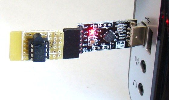
Modern PCs are no more equipped with serial ports and therefore this project requires a USB-UART adapter that enables very easy connection of the PIC12F1822 to the PC via the USB port. You can get them really cheap on ebay. I bought one for $3.39 (see the picture below) from here: http://cgi.ebay.com/ws/eBayISAPI.dll?ViewItem&item=370532286388
It can be directly interfaced to the TTL input and output of EUSART module of PIC12F1822. This module also provides +5 V, +3.3 V, and ground terminals. The power supply for the microcontroller circuit is derived from the same +5 V and ground pins.

On PC’s side, the open source programming language Processing is used to receive the ADC output and convert it into the actual temperature. The temperature is displayed on a graphics window on the computer screen in numeric format as well as with a wall tube thermometer looking image where the level of alcohol rises with increasing temperature. A clickable Start/Stop button also appears on the window to enable or disable the data logging.

Circuit diagram

The circuit diagram of this project is pretty simple. The microcontroller reads the temperature sensor’s output through RA2/AN2 pin and convert it to a 10-bit digital number. The Tx (RA0) and Rx (RA1) port of the EUSART module are connected to the corresponding pins of the USB-UART module. The microcontroller runs at 4.0 MHz using an internal clock source. Although I have disabled the MCLR function here, you can use it for an external reset if you want.


For more detail: Low cost temperature data logger using PIC and Processing using PIC12F1822

The post Low cost temperature data logger using PIC and Processing using PIC12F1822 appeared first on PIC Microcontroller.
Revised version of LM35 based digital temperature meter using PIC16F688

$
0
0

This is a revised version of my LM35 based digital thermometer project that I posted last year. Although it is one of the simplest projects, it is very popular among newbies who are just starting to learn microcontrollers. There was a little flaw in the original project as pointed by some readers. I was using a 1.2 V reference for A/D conversion with PIC16F688 microcontroller. However, the PIC16F688 datasheet says Vref should be equal to or higher than 2.2 V to ensure 1 LSB accuracy of A/D conversion. Here, I am rewriting the same project but this time I am using a MCP1525 IC to generate a precise 2.5 V reference for A/D conversion. This will improve the accuracy of temperature measurements.

digital temperature meter

Theory

The LM35 series of analog temperature sensors are produced by National Semiconductor Corporation and are rated to operate over a -55 °C to 150 °C temperature range. These sensors do not require any external calibration. The output voltage is proportional to the temperature, and the temperature-to-voltage conversion factor is 10 mV per °C. The sensor does not have any DC offset output voltage (which means the output is 0V at 0 °C temperature) and therefore, a negative voltage source is required in order to measure temperatures below 0 °C. For simplicity, the setup shown here is made to measure temperatures above 0 °C only. The PIC16F688 microcontroller reads the analog output voltage from the sensor through one of its ADC channel and derives the temperature information out of it.

For the maximum temperature value of 150 °C, the output voltage of the sensor would be 150 x 10 mV = 1. 5 V. If we use Vref = 5.0 V (power supply voltage) for A/D conversion, the resolution would be poor as the input signal goes only up to 1.5 V. Besides, if the supply voltage is not stable, it won’t be a good idea to use it as  Vref for A/D conversion. Using a lower and more stable Vref voltage can improve both the resolution and the accuracy of A/D measurements. However, the datasheet of PIC16F688 microcontroller recommends to use reference voltage above 2.2 V to ensure 1 LSB accuracy of A/D conversion. The MCP1525 IC from Microchip provides a precise output voltage of 2.5 V, which could serve this purpose. This device is also available in TO-92 package, and therefore, it can be wired on a breadboard too.

Circuit diagram

The revised circuit diagram of the project is shown below. All the connections remain the same, except the two diodes and a resistor in the original circuit are replaced by a MCP1525 device.

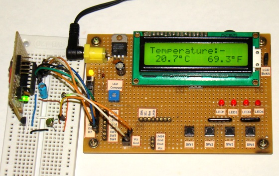
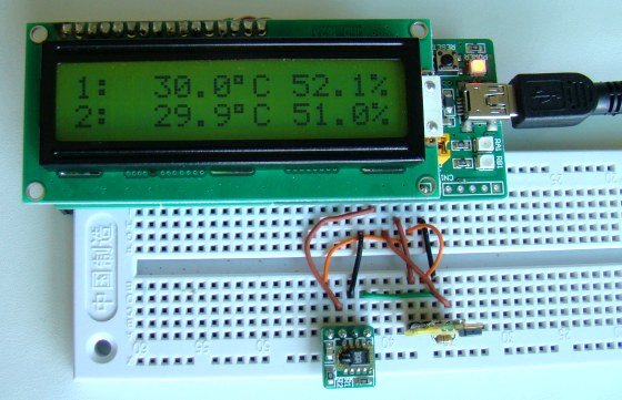
The whole setup of this project is shown below. For illustrative purpose, I am using the LCD display from my I/O board project here. Don’t get confused with all the LEDs and tact switches on the board, they should be disregarded. I am only using the LCD part of it.


For more detail: Revised version of LM35 based digital temperature meter using PIC16F688

The post Revised version of LM35 based digital temperature meter using PIC16F688 appeared first on PIC Microcontroller.
Humidity and temperature measurements with Sensirion’s SHT1x/SHT7x sensors using PIC18F2550 (Part 1)

$
0
0

Temperature and relative humidity are two very important ambient parameters that are directly related to human comfort. Sometimes, you may be able to bear higher temperatures, if there is a lower relative humidity, such as in hot and dry desert-like environment. However, being in a humid place with not very high temperature may make you feel like melting. This is because if there is high relative humidity, sweat from our body will evaporate less into the air and we feel much hotter than the actual temperature. Humidifiers and dehumidifiers help to keep indoor humidity at a comfortable level. Today we will discuss about Sensirion’s SHT series of digital sensors, more specifically SHT11 and SHT75, which are capable of measuring both temperature and relative humidity and provide fully calibrated digital outputs. We will interface both the sensors to PIC18F2550 microcontroller and compare the two sets of  measurements to see the consistency between the two sensors. This tutorial is divided into two parts. The first part will cover all the details regarding the sensors, including their specification, interface, and communication protocol. The second part will be more focussed on the circuit diagram, implementation of the communication protocol with PICMicro, and the results.

Sensirion’s SHT1x

Theory

Sensirion offers multiple SHT series of digital sensors for measuring both relative humidity and temperature. The temperature is measured using a band-gap sensor, whereas the humidity sensor is capacitive; which means the presence of moisture in air changes the dielectric constant of the material in between the two plates of a parallel-plate capacitor, and hence varies the capacitance. The required signal conditioning, analog-to-digital conversion, and digital interface circuitries are all integrated onto the sensor chip. The various SHT series sensors have different levels of accuracy for humidity and temperature measurements, as described below.

SHT1x, 2x, and 7x series of humidity sensors (Source: http://www.sensirion.com)

SHT1x are available in surface mount type whereas SHT7x are supplied with four pins which allows easy connection. The SHT11 and SHT75 sensors both provide fully calibrated digital outputs that can be read through a two-wire (SDA for data and SCK for clock) serial interface which looks like I2C but actually it is not compatible with I2C. An external pull-up resistor is required to pull the signal high on the SDA line. However, the SCK line could be driven without any pull-up resistor. The signaling detail of the serial bus is described in the datasheet, which we will implement for PIC18F2550 microcontroller using mikroC pro for PIC compiler. The operating range of both the sensors is 0 to 100% for relative humidity, and -40.0 to 123.8 °C for temperature. The sensor consumes 3 mW power during measurement, and 5 μW, while in sleep mode.

The SHT11 module that I have got is from mikroElektronika. The sensor (SMD) is soldered on a tiny proto board with all the four pins accessible through a standard 0.1 inch spacing male header. The board comes with pull-up resistors connected to both SDA and SCK lines. One concern in this type of arrangement is the heat dissipated by the pull-up resistors could affect the measurements if the resistors and the sensor are close in the board. We will discuss about this issue later too. The SHT75 module from Sensirion, however, does not include any pull-up resistor for SDA line and therefore must be included externally.


For more detial: Humidity and temperature measurements with Sensirion’s SHT1x/SHT7x sensors using PIC18F2550 (Part 1)

The post Humidity and temperature measurements with Sensirion’s SHT1x/SHT7x sensors using PIC18F2550 (Part 1) appeared first on PIC Microcontroller.

Enhanced 5/2-day Central Heating Programmer with serial computer interface using PIC16F628A

$
0
0

Overview

This project has come about from my desire to control my home heating from work.  As I have a VPN between work and home a straightforward relay controlled from a PC would seem the easiest solution.  However I also wanted a control unit that I could operate in the house without resorting to the computer.  For example, I get up late and the heating is off, I just want to hit a button and turn it on.  In fact the programmer shown on this page is now next to my bed so I can turn the heating on before I  get up late, and also switch it off if I turn in early, which helps save on the fuel bills J

Features

  • Independent control for heating and hot water.

  • 10 flexible program entries.

  • Programs can be set to operate Mon-Fri / Sat-Sun / Mon-Sun.

  • Manual advance for water and heating

  • Water and heating can be independently set to manual or programmed control.

  • Operation and setup from front panel or remote serial CLI

  • Battery backup for Real Time Clock (RTC), program settings and manual control.

  • Programmer can be located remotely from boiler using low voltage signals over CAT5 or 6-core alarm cable.

  • RS232 serial interface with command line interface allows full control and setting from any computer.

  • Front panel control can be locked-out from serial CLI

  • Based on Microchip PIC 16F628A microcontroller

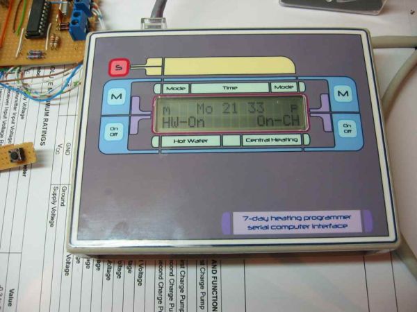
This programmer has been designed for use with a domestic heating boiler.  It provides outputs via two relays to control the supply of Hot Water and Heating.  There are 10 program entries available and each one can control the heating and water independently. The programmer allows manual advance of the heating and water and  disabling of program control, useful if you’re going away for a few days and want to leave the heating and water off. As well as providing normal front panel switch control of the heating and water, the programmer also features a serial terminal interface that allows it to be operated remotely from a PC running a Terminal Emulator.

Central Heating Programmer

The program entries can be set to switch weekdays only, weekends only or everyday but not individual days.  I believe a programmer that can switch weekdays or weekends is a 5/2-day programmer so I would call mine a 5/2/7 day programmer since it can do the whole week as well.  However, a 7-day programmer is one that can do individual days so I’ve settled on calling mine an Enhanced 5/2-day programmer.

The programmer and boiler control relays are contained in separate units so that the relays can be located close to the boiler while the programmer itself can be located anywhere in the house using low voltage connections back to the relay unit.  The connection between the programmer and relay unit requires six wires for power, serial data and relay controls making it possible to use 6-core alarm cable or, as I have done, operate it over the CAT5 UTP cabling installed throughout my house.  Of course it’s quite simple to build it as a single unit if that suits the application.  There is also no reason why you can’t make the serial interface connection local to the programmer in which case you only need 4 wires for power and relay controls.

If you don’t require the remote computer CLI the programmer is fully functional using just the front panel and likewise, if the front panel isn’t required, it can be fully controlled from the serial interface and the LCD and switches omitted from the hardware.


Software

The latest version of the programmer ready .HEX file is provided here.

Firmware Version 2.0.2 28 May 2005
Please read conditions of use and disclaimer before downloading

Developed using MPLAB V7.10 and Oshonsoft PIC Simulator IDE. Assembled with MPASM v04.00

The software is fully functional and the system as described on this web page is currently working with my domestic heating system.  I’ve been using prototypes since March 2005.  The latest code, Version 2.0.2, has been running since 28 May 2005.  As of 17 January 2011 it’s still working and has proved to be 100% reliable.

This is the final version of the code. I’m not going to develop it any further since the programmer now implements all the features I want and works as I intended.  I will do maintenance code releases to fix any software related bugs / issues reported to me.

Known issues

  • no known critical issues.

  • Some CLI commands allow superfluous text on the line after the command. The command executes correctly and any superfluous text is ignored.

  • Please send any bug reports to

    Contact us:

Functionality as designed

  • The current relay output and manual mode settings are stored in NVRAM. In the event of a power failure these are restored when the power resumes. If a programmed setting should have applied at a time during the power outage, it will not get applied when the power is restored. The saved settings that were active at the time of the power failure will be reapplied. 

  • When in front panel setup mode, no programmed outputs will be activated. If a programmed setting should have applied while the programmer was in setup mode, it will not get applied on exit. 

  • On power up the programmer sends a VT100 [ESC] c command to the terminal to reset it. This may cause extraneous characters to be displayed or other issues on a non VT100 emulator.  

  • Time is displayed / entered in 24 hour format only. 

  • Serial interface operates at 9600bps, 8 bits, 1 stop, No parity.  Baud rate is not configurable

  • When in front panel setup mode the serial CLI is disabled.

Code Revisions

V2.0.3

  • As version 2.0.2 code but without the CLI diagnostic commands. These commands where implemented from an include file which has simply been omitted during assembly for V2.0.3. 

V2.0.2

  • Enabled the PIC Watch Dog Time (WDT) and added supporting code.

  • New command ‘dw’ shows number of Watch Dog timeouts that have occurred since power-up. These should not occur if the programmer is functioning correctly, if they do this alerts you to a potential problem.

  • Implemented front panel setup functions. Allows time to be set. Program entries to be viewed, cleared, entered and edited.

  • Changed handling of serial CLI input buffer overflow. The behavior is now consistent with handling of unknown commands. 

  • The CLI ‘p’ command now shows output control for Hot Water followed by Central Heating. This is the opposite way round to firmware before V2.0.0 

V1.9.1

  • Added CLI command to enable / disable front panel control. This has been added to allow the front panel to be locked out when using automated control of the unit from the CLI.  It also provides a way to stop my girlfriend from turning the heating on all the time:-)

  • CLI relay control command letter has been changed from ‘t’ to ‘u’. 

  • The relay control and manual mode CLI commands worked by inverting the current setting.  This has now changed so that the setting for on/off or manual/programmed is explicitly specified on the command line. 

  • Moved the on/off text for heating and water on the LCD to the extreme ends of the display. This is to allow the display of the text ‘Locked’ when the front panel is disabled.

V1.9

  • Prior to FW V1.9 the LCD display had the text CH- and -HW on the second line but as the programmer is now cased and the front panel artwork has legends on it, this text has been removed from the V1.9 code.

  • The manual mode status was indicated with the characters ‘m’ and ‘p’. This has now been replaced by the text ‘Man’ and ‘Prg’

  • Added CLI function to send a VT100 [ESC] c command to the terminal to reset it. 

  • Send VT100 [ESC] c command to the terminal at power-up.

  • Added command to return an ASCII hex byte with the current status of the relay outputs and manual mode settings. For use with automated control of the CLI.

  • Improved the CLI ‘p’ command entry format and parsing.

  • Made program control for CH and HW outputs fully independent by adding a no-change flag and enabling this feature within all related functions.


Hardware

The hardware for the programmer comprises two units.  The first contains the two relays that switch the mains power to control the boiler.  This also has an RJ45 socket to allow connection into a CAT5 cabling system that takes power, serial data and relay control input signals to the second unit, an intelligent programmer.  There is also a 2.1mm DC power socket that is used to connect an external 9~12V DC power adapter. This supplies power to the relay board and the programmer controller. A 9-pin ‘D’ socket provides connectivity to a PC serial interface.

For more detail: Enhanced 5/2-day  Central Heating Programmer with serial computer interface using PIC16F628A

The post Enhanced 5/2-day Central Heating Programmer with serial computer interface using PIC16F628A appeared first on PIC Microcontroller.
Roll and Temperature sensor applications using PIC18F2550

$
0
0

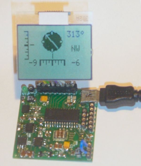
This page will show you how to use the TD-CMP modules in a way which fits you most.


Here are the technical specifications of the modules:

  • Compass: Resolution: 1° – Accuracy: 3°
  • Tilt/Roll: (TD-CMP02 and TD-CMP03 only) Resolution: 2° – Accuracy: 5°
  • Temperature: (TD-CMP03 only) Resolution= 1°C/F – Accuracy =1°
  • New: Sampling rate: 12,5 to 25 samples/second.
  • Easy Tilt/Roll calibration.(TD-CMP02 and TD-CMP03 only)
  • Interfaces: I²C, RS232 and mini-USB (as a HID device: PID=0461, VID= 1023)
  • Powered by USB bus or an external 5V.
  • Direct LCD readout possible. LCD contrast by user.
  • Low power LED lights when facing North (angle within 11,25° both left and right from North.)
  • USB Windows application (written in C#) available for free download.) Compatible with WinXp/Vista.
  • Source code (CCS C and C# .NET) and schematics (Eagle) can be purchased separately.
  • Module software is 100% upgradable with a simple bootloader.
  • PCB Dimensions: 40 x 41 mm or 1″57 x 1″61, weight: 10 grams.

Temperature sensor

These assembled modules are available from our online shop.

You may also purchase the bare pcb, a KIT DIY* version and the source code. KIT step-by-step construction guide.

New: compass calibration.

Schematics and pcb diagrams available for download. Last update: November 26, 2009.

DIY* = Do It Yourself

Power Source: JP4: Connect pin 2 to pin 3 to power the module directly from USB. Connect pin 1 to pin 2 when powered externally via JP3, pin 1.

New: Increase sampling speed from 12,5/second to 25/second: connect SPEED1 to SPEED2 (JP3, pin4 to JP3, pin2.)

LCD contrast Adjust: Connect pin 5, JP3 to +5V before powering up. Release when the desired the contrast is reached.


Tilt/Roll Calibration: (TD-CMP02 and TD-CMP03 only):

  • First place the module on a completely flat surface, power up.
  • Then shortly apply +5V (pin 1, JP2) to ADJUST (pin 5, JP3) Release after 1 second.
  • Check readings when applying tilt/roll to the module. Repeat the calibration procedure if necessary. Done.


Compass Calibration: (do not touch the PCB or chips whilst calibrating.)

  • First place the module on a completely flat surface, power up, head to North (position as shown in diagram and picture above), then turn the module slowly 360° (make 2-3 full clockwise and/or counter-clockwise spins.)
  • Now apply +5V (pin 1, JP2) to ADJUST (pin 5, JP3) Wait for 8-10 seconds; the LED will flash 3 times. Release the ADJUST pin from +5V. Power off and on.
  • Check compass readings when heading the module to N, S, E, W. Repeat the calibration procedure if necessary. Done.


Module RESET: apply GND to MCLR pin.


Temperature sensor: (TD-CMP03 only): The external LM335Z sensor connects to JP3 pin 4 and 6. No temperature will be displayed when the sensor is removed.


RS232 interface:

JP2 provides the interface to connect to your COM port and hyper terminal. Communications @ 115200 bpS, 8N1.

Use a level converter like the MAX3232 between the TD-CMP module and the pc serial port. See this example.

Also used for bootloading (module software update.) Check under the download section below for the latest version. Bootloading of the HEX-file can be done with Tiny Bootloader 1.91


For more detail: Roll and Temperature sensor applications using PIC18F2550

Current Project / Post can also be found using:

  • pic16f877a temperature projects

The post Roll and Temperature sensor applications using PIC18F2550 appeared first on PIC Microcontroller.
Homemade temperature LED display for PC using PIC16F876

$
0
0

Since I started my watercooling prejoect, I have been verry interested in how well it perform,
the only way is to measure all temperatures before and after,
The motherboard temperature sensors is useless unacurate, so I’m using LM50B

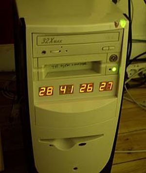
temperature LED display
By using this LM50B sensor I get 1 C of real accuracy
I use a PIC16F876 to drive a four two digits LED displays, the PIC16 has 4 analog inputs with 10 bits resolution,
now I can display 4 temperatures at the same time to monitor performance :-)
I monitor CPU, Chipset, GFX card, Harddisks.

Here is the schematic good old handdrawn original..
Here is the schematic Re-Drawn Maybe you like this better :-) OK, comments for the circuit:
You can use any number of LED displays: 2, 4, 6, or all 8, depending on how many temperatures you want to display,
LED display type must me common cathode, FET can be any N-FET type you have, I have used IRF530 I had on stock,
NPN transistors can also be used if you dont have fets, then remember to mount a 1k resistor on each base inpus.
Each sensor input connector is protected using a 1k resistor, so you can connect sensors with power on,
nothing will burn if you connect it wrong.
Only calibration requred is the refference voltage, it need to be exactly 2.5600 volt, I have used a super stable regulator,
but an LM317 can also be used to make 2.56 volt with if that is what you have. DOWNLOAD The HEX file for the PIC16F876.
The 5 volt supply is taken from a free harddrive power connector, no need to regulate it, 4.8 to 5.2 will work fine.
This complete circuit with 8 all digits consume about 100mA. Good Luck.


For more detail: Homemade temperature LED display for PC using PIC16F876

The post Homemade temperature LED display for PC using PIC16F876 appeared first on PIC Microcontroller.

Temperature controlled fan using PIC 16F877A

$
0
0

You might have come across several applications where we need to control a specific device based on analog parameter. This Embedded system works in a similar concept where we are about to control the speed of a DC motor using based on the external temperature. The rise in temperature will result in increase in speed of the motor and vice versa. These type of Temperature controlled fan systems can generally be used to maintain temperature of a room or object automatically.

Temperature controlled fan using PIC 16F877A DESIGN OF TEMPERATURE CONTROLLED FAN SYSTEM:

  • The temperature is measured by means of a temperature sensor LM35.
  • The output voltage of the sensor is fed to the A/D channel of the Microcontroller.
  • Based on the sensed temperature the speed of the motor is controlled using PWM .
  • Several temperature ranges was set in the code to vary the motor speed based on the level of temperature sensed.
  • The speed of the motor is controlled by using PWM.

Lm 35 is used to sense the external temperature which is capable of sensing temperature ranges from -55 to 150 C. The output voltage is proportional to the temperature hence there is no need of trimmers to calibrate the reading. The output voltage of this sensor varies by 10mv per degree change in temperature.

Temperature controlled fan using PIC 16F877A SchematicCALIBRATION:

We are using a 10 bit ADC and Vcc as Vref to the ADC module of the Controller. So in order to determine the step size we have to divide the Vref by our resolution that is 2^10 ( 1024 ).

Step Size = 5 / 1024 = 4.83mV

We obtain a change of 10mV with each rise or fall in temperature from the sensor. And value in the ADC register will alter by two steps with each degree change in the sensor since two increments of step size i.e 4.833mV * 2 = 9.96mV which is approximately equal to 10mV. So in order to obtain the original value we have to divide the contents in the ADC register by 2


For more detail: Temperature controlled fan using PIC 16F877A

The post Temperature controlled fan using PIC 16F877A appeared first on PIC Microcontroller.
Single Chip Temperature Data Logger

$
0
0

Introduction

A data logger is a device that records measurements over time. The measurements could be any physical variable like temperature, pressure, voltage, humidity, etc. This project describes how to build a mini logger that records surrounding temperature values. It has following features:

- Uses just one 8?pin chip, so very compact size circuit.
– Temperature range: 0 to +125°C.
– Can store up to 254 measurements.
– Sampling interval options: 1 sec, 1 min, 10 min
– Reset feature to clear all previous measurements.
– Serial transfer of recorded measurements to a PC
– Three tactile switches for user inputs and a LED indicator.

Single Chip Temperature Data Logger Description

The beauty of this project is that it uses just a single chip for logging. It is PIC12F683, an 8?pin microcontroller from Microchip. PIC12F683 has six general purpose I/O (GP0?GP5, GP3 is input only) pins, and 2K x 14 Flash program memory
with 256 bytes of internal EEPROM.

Temperature will be measured with a DS1820 temperature sensor. DS1820 is a one wire digital temperature sensor from Dallas Semiconductor (now MAXIM). The operating temperature range of the device is -55°C to +125°C with an accuracy of ±0.5°C over the range of -10°C to +85°C. The temperature sensor output is 9?bit Celsius temperature measurement, and so the temperature resolution corresponds to the least significant bit, and which is 0.5°C. But in this project we will use only the most significant eight bits. Therefore, the temperature resolution will be 1°C. The measured temperatures will be recorded into the internal EEPROM memory of PIC12F683.

The first location of the internal EEPROM will store the sampling interval of data logger. Sampling interval defines the time gap between two successive measurements. This project will have 3 options for sampling time: 1 sec, 1 min, and 10 min. These are user selectable. The second location of EEPROM will store the number of measurements recorded so far. And the remaining 254 EEPROM locations will store 8?bit temperatures. So, using 10 min sampling interval, 254 bytes of EEPROM will provide data logging for 42 hours. The recorded measurements can be sent to PC at any time through a serial link at 9600 baud.

User Inputs

There will be three tact switches for user inputs, namely Start, Stop, and Send/Reset. The three switches will be able to accept the following 4 user requests.

1. Start: When ‘Start’ button is pressed, data logging starts.
2. Stop: Once the ‘Stop’ button is pressed, data recording will stop.
3. Send: Transfer data to PC through serial port.
4. Reset: Holding the ‘Send’ button for 2 sec or more clears the internal EEPROM memory.

Single Chip Temperature Data Logger SchematicSampling Time Selection


The sampling interval can be selected as 1 sec, 1min, or 10 min using the same three switches. Suppose if we need 1 min sampling time, first turn OFF the power, then hold the ‘Stop’ button, turn the power ON, and wait till the LED glows. Once the LED glows, release the button, and the sampling interval will be set to 1 min. The new set sampling time will be updated to EEPROM location 0 so that in case of power failure, the previous sampling time will be restored. Similarly, use ‘Start’ and ‘Send’ buttons for 1 sec, and 10 min sampling intervals respectively.

LED Indicator

Every time the user presses input buttons, LED glows for a moment to indicate that the input is accepted. It also blinks thrice every time EEPROM Write operation takes place. It also blinks at the beginning when the power is turned ‘ON’. It also glows when the EEPROM memory is full.

For more detail: Single Chip Temperature Data Logger 

The post Single Chip Temperature Data Logger appeared first on PIC Microcontroller.
Viewing all 121 articles
Browse latest View live


<script src="https://jsc.adskeeper.com/r/s/rssing.com.1596347.js" async> </script>