Quantcast
Channel: Temperature Measurement Projects - PIC Microcontroller
Viewing all 121 articles
Browse latest View live

Online Monitoring of Temperature of Conductors Using Zigbee and GSM

$
0
0

Project Summary

An on-line monitoring system of temperature of conductors and fittings based on GSM SMS and Zigbee is produced in this project, by which the temperature of conductors and fittings can be monitored in real-time and some accidents caused by the increased temperature can be avoided. The principle and the feature of GSM SMS and Zigbee communication are analyzed. The construction of this system is outlined, and the force modal of calculating the variety of the sag due to the increased temperature of conductors is built. The Zigbee communication module is produced based on RF4CE standard. Finally, the software and hardware design of the online temperature monitoring unit of conductors and fittings are outlined.

Project Description

With fast development of economy in India, the demand of electricity is higher and higher, and the problem between lag of construction of network and inadequacy of transmission capacity becomes increasingly prominent, which exacerbates the unharmonious contradictions of development between power grids and power generation structure. Some provinces and cities have begun to take power limited policies to alleviate contradiction of the current electricity supply-demand, how to resolve this problem has become imperative responsibility for many power workers. Recently, in order to prevent overloading of transmission lines, domestic power system usually adopts the static, conservative transmission capacity value in design, which is a conservative static value based on the severest weather conditions.
Online Monitoring of Temperature of Conductors Using Zigbee and GSMHowever, such severe weather conditions rarely occurred, and it has resulted in the inefficient use of potential transmission capacities in most time. In the situation of “east-west power transmission, south-north power transaction, nationwide electricity interconnection”, long-distance, large-capacity and high-voltage transmission lines will be more and more. By 2010, the transmission capacity of some main lines of 500 kV will reach or exceed 1 GW. By 2020, the transmission capacity for most lines of 500 kV will reach 1 ~ 1. 5GW. Some normal current for heavy short lines will reach 2 GW, which will be near 3 GW in accidents. Now, according to the traditional technology, the transmission capacity can be increased only by adding transmission lines. However, it is becoming more and more difficult to build new transmission lines with the transmission lines increased.

From the perspective of sustainable development and environmental protection, we should pay more attention from power grids expansion to increase the potential transmission capacity of available transmission lines, and enhance the transmission capacity of power grids, so as to resolve the problems between high requirement of electricity and difficulty of new transmission line. In March 2005, the State Grids held a particular meeting about improving the transmission capacity of power grids in Beijing, the meeting pointed out that at the same time of building main electrified wire netting of super high voltage, we need actively and fully tap the potential of existing capacity. At present, some areas adopt the allowable temperature value of 70 to 80 or even 90. Properly increasing the allowable temperature of existing conductors can increase stable carrying capacity of transmission lines, thereby the normal transmission capacity is improved. The method is a breakthrough of current technical regulations, the impact caused by improving conductor temperature on conductors, the mechanical strength and the lifespan of matched fittings, the increase in sag and so on should be studied. In addition, if the conductor temperature and the sag can be real-timely monitored, the dynamic regulation of the transmission capacity, such as day and night, cloudy and sunny, summer and winter under the different environmental conditions can be realized to improve the transmission capacity. In order to meet these demands, an on-line monitoring system of temperature of conductors and fittings based on GSM SMS and Zigbee is studied and developed in this paper.

Introduction to GSM SMS, ZigBee and LM35

A. GSM SMS
GSM (Global System Mobile Communications) is a global digital mobile communication system, whose coverage is the most widely, phone owners is the largest, and reliability is very high. SMS (Short Message Service) is a kind of short message transmitted. In fact, the information transmission is achieved by receiving and sending text message in the businesses center between mobile phones and other short message carriers, and the businesses center is an independent operating system of GSM network whose main function is submitting, storing, and transferring short message. SMS is a special and important service as well as calling for users by GSM system. In this project, a self-designed industrial GSM module is selected to finish the transmission and the decoding of the monitoring data through AT command and coding of short message PDU (Protocol Data Unit).

B. ZigBee
ZigBee wireless network technology is a new standard launched and made by ZigBee Alliance. The alliance, founded in August 2001, is a fast-growing and non-profit organization, and it aims is to provide consumers with more flexible and easier electronic products. The second half of 2002, four large corporations including the British company Invensys, Mitsubishi Electric Corporation, Motorola and the Dutch giant Philips Semiconductor Corporation jointed together to announce that they would join the “ZigBee Alliance” to invent the next-generation wireless communication standards named “ZigBee”, which became a significant milestone in the development process. In October 2004, the ZigBee Alliance announced a version 1.0 of ZigBee protocol, and in December 2005 version 1.1. ZigBee uses free frequency bands of 2.4 GHz and 900 MHz, and its transmission rate is 20 kbps to 250 kbps. In this paper, the perfect chip cc2430 is selected to design the wireless hardware platforms of ZigBee, a standard ZigBee wireless network module is produced, and a reduced version of ZigBee wireless network protocol is programmed. The Zigbee module and protocol have been successfully applied to power system, medical and some other fields.

ZigBee is the set of specs built around the IEEE 802.15.4 wireless protocol. The IEEE is the Institute of Electrical and Electronics Engineers. They are a non-profit organization dedicated to furthering technology involving electronics and electronic devices. The 802 group is the section of the IEEE involved in Information technology—Telecommunications and information exchange between systems—Local and metropolitan area networks including mid-sized networks. Group 15.4 deals specifically with wireless networking (Wireless Medium Access Control (MAC) and Physical Layer (PHY) Specifications for Low-Rate Wireless Personal Area Networks (WPANs) technologies.

Network Topologies
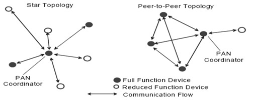
Depending on the application requirements, an IEEE 802.15.4 LR-WPAN may operate in either of two topologies: the star topology or the peer-to-peer topology. Both are shown in Figure. In the star topology the communication is established between devices and a single central controller, called the PAN coordinator.

Online Monitoring of Temperature of Conductors Using Zigbee and GSM SchematicTemperature Measurement
Temperature can be measured via a diverse array of sensors. All of them infer temperature by sensing some change in a physical characteristic. Six types with which the engineer is likely to come into contact are: thermocouples, resistive temperature devices (RTDs and thermostats), infrared radiators, bimetallic devices, liquid expansion devices, and change-of-state devices.

The Overall Structure of Online

Monitoring System
The online monitoring system of temperature of conductors and fittings based on GSM SMS and Zigbee is mainly composed of the municipal monitoring center, the communication unit, the temperature monitoring unit and the expert software, the topology of system is shown in Fig.1. The communication unit is installed on the tower with both GSM and Zigbee communication modules, and the temperature monitoring unit on the corresponding conductors with the same potential.


For more detail: Online Monitoring of Temperature of Conductors Using Zigbee and GSM

Current Project / Post can also be found using:

  • projects of temperature measurement devices
  • Temperature controller Using PIC 16f877a DS18B20 rs232
  • temperature controller using pic 18F4550
  • temperature controller using pic microcontroller project

The post Online Monitoring of Temperature of Conductors Using Zigbee and GSM appeared first on PIC Microcontroller.
Weather meter using PIC 16F877 Microcontroller

$
0
0

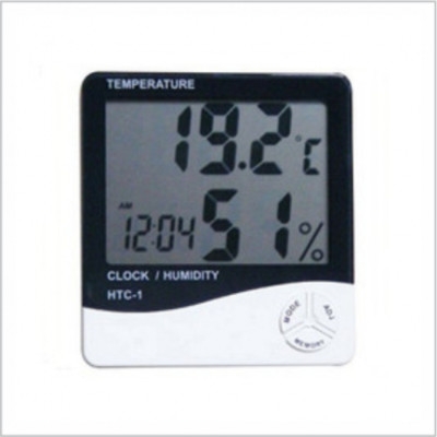
Weather monitoring systems are available in plenty and these are pretty handy gadgets we use in our daily life for weather forecasting and other purposes. But these kinda gadgets might be expensive and may not be available for customization to our specified purpose. To overcome these advantages you can build this customized weather meter using PIC microcontroller which won’t cost much like those gadgets.

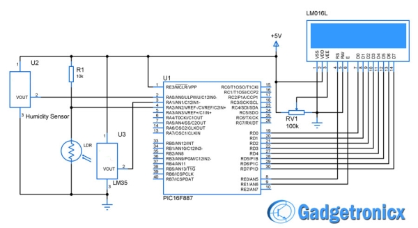
The system is built around PIC microcontroller where three parameters are measured in this system. Humidity,Temperature and ,Light intensity are the parameters this system takes as input to understand the weather condition. Then these parameters are displayed in the LCD screen for the user.

Weather meter using PIC 16F877 MicrocontrollerLM35 was used as a temperature sensor which is capable of sensing temperature ranging from -55 C to 150 C. The output voltage will be proportional to the temperature hence there is no need of trimmers. The output voltage of this sensor varies by 10mv per degree change in temperature.

Bought this Humidity sensor from a local store. The obtained output voltage is scaled to percentage and the reading in means of percentage is displayed in the LCD.

Simple LDR is used to measure the light intensity of the environment. Here LDR was used along with a resistor to form a voltage divider and the output is obtained from that divider. This output is also scaled to percentage and displayed in the LCD for the user.

Weather meter using PIC 16F877 Microcontroller Schematic

ALGORITHM:

  1. Initialize the LCD display.
  2. Display “H” , “L” and “T” which represents the parameters Humidity, Light intensity and Temperature.
  3. Define various weather conditions such as Sunny, rainy ,etc  for the expected sensor readings.
  4. Initialize the ADC Channels for the respective sensors.
  5. Read the sensor output one by one.
  6. Make appropriate conversion of the ADC value.
  7. Display the sensor values in the LCD display for the user.


For more detail: Weather meter using PIC 16F877 Microcontroller

Current Project / Post can also be found using:

  • temparetor mesure by pic

The post Weather meter using PIC 16F877 Microcontroller appeared first on PIC Microcontroller.
Arduino powered temperature sensing RGB LED nightlight using PICaxe

$
0
0

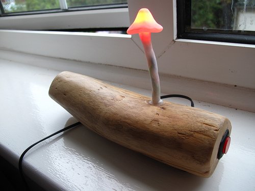
About a year ago I started on a project to make a temperature controlled nightlight. I was inspired by seeing these lovely LED lamps styled as mushrooms growing out of pieces of wood. Those mushrooms were made out of glass, which was somewhat beyond my skills. However I then saw some had used translucent sculpey to make mushroom nightlights on instructables. So with that discovery it seemed like it would be rather simple to do…

temperature sensing RGB LED nightlight

The first job was to solder up a three colour (RGB) LED (a super bright one from oomlout):

I then covered the LED in translucent Fimo:

As Fimo only needs to be heated to about 100C to set it’s ok to do this, as it won’t hurt the LED. Also LEDs don’t normally give out much heat, so covering them is ok. Of course this is a relatively low power (though quite bright) LED as well which helps.

I found a branch on the way home from work, which I cut up and sanded down. This formed the base for the mushroom:

As you can see I also opted for a chunky on/off button, in the style of the original mushroom lamps.

Next I put a small electronics project box into the bottom of the piece of wood and made space for a slide switch and power socket

At the time I decided to try to use a Picaxe 08m chip to control the LED and read from a temperature sensor. The Picaxe 08m has a native function to read the temperature from a DS18B20 One Wire digital temperature sensor. It also had just about enough inputs and outputs to handle controller the three colors of the LED and reading from a slide switch (to make it switch between temperature display and plain nightlight). The individual chips were also pretty cheap, so it seemed like a good plan at the time.

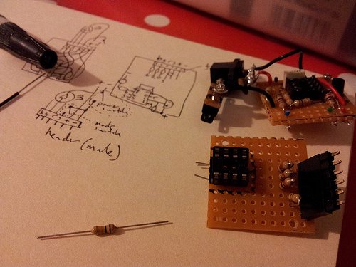
However the size of the circuit and number of components I needed to solder was all a bit too much for me:

temperature sensing RGB LED nightlight circuit

Eventually after much debugging I was able to get some things working – e.g. controlling the colour of the LED, but the temperature sensor just wouldn’t cooperate and always gave a high reading. I also managed to get through a few sensors due to mis-wiring them!

So I decided it was time to start again with the circuit. I bought a better soldering iron (a not too expensive digital temperature controlled one) and started on a new circuit:


For more detail: Arduino powered temperature sensing RGB LED nightlight using PICaxe

The post Arduino powered temperature sensing RGB LED nightlight using PICaxe appeared first on PIC Microcontroller.
Refregirator Temperature Controller Project (Save Your Electricity Bill)

$
0
0

In This Post we discuss about How to build a Refregirator Temperature Controller using Microcontroller.

This Project is Development of Thermo meter project.

Suggested Page>> MIcrocontroller Based Thermo meter project

Mainly we use Mikro C Programming Language in this Project and ISIS Proteus Software use for testing Purposes.

Refregirator Temperature Controller Project (Save Your Electricity Bill)How to Work Refregirator Temperature Controller.

You know about Refregirator has Internal Heater Coil inside the freezer Area. These heater use for melt ICE inside the freezer.Heater take lot of power units consumption for melting ICE.This is effect highly for refregirator total power consumption.We cut that extra power Units using this Refregirator Temperature controller.This project is very effective for Chest Freezer.

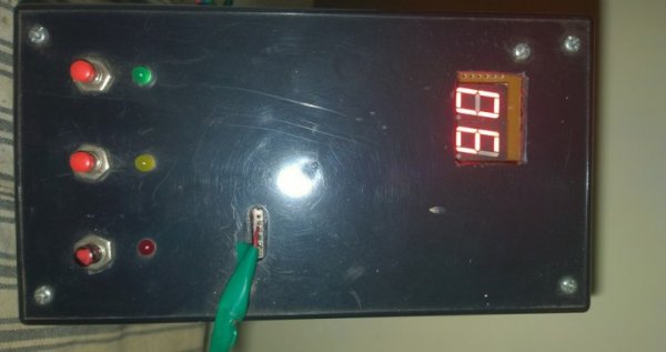
We placed DS18B20 Sensor inside the Refregirator and every time it measure refregirator Inside temperature on Two 7 SegmentDisplay.If Refregirator Inside Temperature reach to Preset ON Temperature and Refregirator Automatically Power On.When InsideTemperature reach Preset OFF Temperature Automatically Refregirator Power OFF.We can setup ON and OFF Temperature Using 4 Buttons.
We use Four Buttons for Setup ON/OFF Temperature in this Refregirator Temperature Controller
1) Mode Button
2) Up + Button
3) Down – Button
4) Save Button

Mode Button
Mode 1 (Press 1 time)
You Can Adjust Refregirator OFF Temperature using + and – Buttons.
You Can Save Changes using SAVE Button(Hold).

Refregirator Temperature Controller Project (Save Your Electricity Bill) SchematicMode 2 (Press Two times)

You Can Adjust Refregirator ON Temperature using + and – Buttons.
You Can Save Changes using SAVE Button(Hold).
We Should Use 4.7k Pullup Resister for DS18B20 .
This Project Succesfully Tested in Real Hardware and Work very well.


For more detail: Refregirator Temperature Controller Project (Save Your Electricity Bill)

Current Project / Post can also be found using:

  • time and temperature display usng pic microcontroller
  • life temperature measurement project
  • pic measurement of tempwrature with ethernet
  • schematic pic16f thermometer

The post Refregirator Temperature Controller Project (Save Your Electricity Bill) appeared first on PIC Microcontroller.
PIC16F877A (with LCD) not working

$
0
0

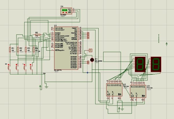
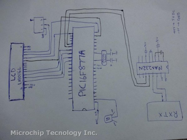
I have designed a PIC18F877A micro controller project to read temperature from an LM35 using ADC, display it on an LCD and transmit it to a serial port.

When the program starts, sometimes it shows a startup message – sometimes it doesn’t display anything.

PIC16F877A (with LCD) not workingAlso, the serial port connection is not working. Can anyone help – am I missing something? Are there any ground connections missing?
My code:
#include
#device adc=10
#fuses HS,NOWDT,NOPROTECT,NOLVP
#use delay(clock=20000000)
#use rs232 (baud=9600,rcv=PIN_C7, xmit=PIN_C6)
#include
float value;
float temp;
float temp2;
float temp3;
float temp4;
float temp5[14];
float count[14];
int c;
void main(void)

PIC16F877A (with LCD) not working schematic{//setup_adc_ports( ALL_ANALOG );//Initialize and Configure ADC
//setup_adc(ADC_CLOCK_INTERNAL );
while(1)
{
lcd_init();
lcd_gotoxy (1,1);
delay_ms(1000);
printf(lcd_putc,” WELCOME TO\n Micro Tech Sol.”);
delay_ms(3000);
lcd_gotoxy (1,1);
printf(lcd_putc,” Fuel Monitoring \n PROJECT “);
delay_ms(3000);}}


For more detail: PIC16F877A (with LCD) not working

Current Project / Post can also be found using:

  • pic 18f452 lcd program pdf
  • Digital Clock Project with 8051 Using LCD pdf
  • pic microcontroller dallas lt temperature measurement
  • Project name of temperature measurement

The post PIC16F877A (with LCD) not working appeared first on PIC Microcontroller.
Quozl’s Temperature Sensor Project using PIC12C509

$
0
0

Introduction

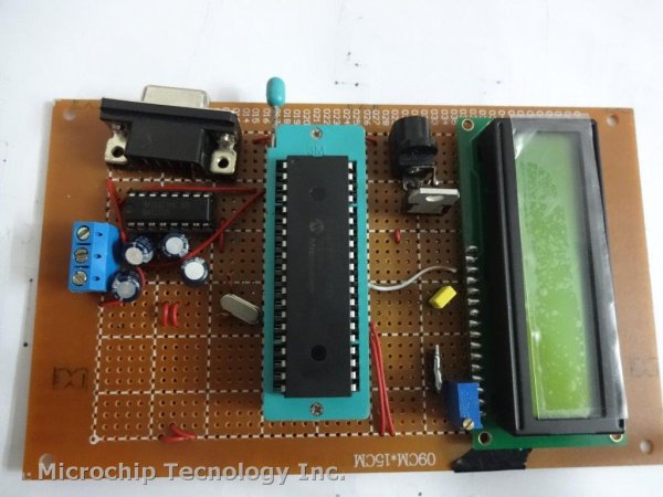
Just a handful of components builds an 8-pin microcontroller based circuit for temperature logging via a serial port; small, fast, and acceptably accurate.

Temperature Sensor

Features

  • provides real-time data to your computer via serial port,
  • interfaces up to four DS1820 temperature sensors,
  • absolute accuracy near 0.5 degrees celcius (as per DS1820 specifications),
  • relative accuracy near 0.01 degrees celcius,
  • speaks in Centigrade or Fahrenheit (selectable by header pins),
  • powered by your computer’s serial port, no extra supply to organise,
  • data format easily processed, no special programs required,
  • minimal parts count reduces cost,
  • built-in serial number for circuit identification,
  • special versions available for exotic requirements; high speed, low speed, additional sensors, long distance or pedantic serial bus.
  • spare inputs can be used as single-bit digital inputs, (feature removed from final version but can be re-inserted),

Applications

A few ideas of how this circuit can be used:

  • simple weather reports for web pages,
  • computer power supply temperature warnings,
  • redundant critical systems monitoring,
  • house temperature monitoring,
  • complex home automation tasks (start fan if warmer outside during winter),
  • refrigerator testing,
  • brewing temperature regulation,
  • fish tank heater verification,
  • microclimate logging (ground versus air temperature),
  • daylight sensing (LDR on digital input),
  • primitive locking (using serial number),
  • remote monitoring of emu fat in a freezer truck,

Availability

The electronics kit maker Kitsrushas released a PCB and kit of this design. Other kit sellers also sell the kit. Here is a summary:


Country Organisation Item Number GPL Compliance Date Checked
Australia Ozitronics K145 Complete 13th June 2003
United States of America Carl’s Electronics Inc CK110 Partial 13th June 2003
Kingston, Ontario, Canada QKits QK145 Complete 13th June 2003
Hong Kong Kitsrus K145 Complete 13th June 2003
Denmark eekit.dk 0104-K145 Partial 29th November 2004

(If you also sell this kit, and you would like to be added to the list, please write to me, including your country, organisation name, links to your web site and to the kit page. There is no reciprocal link condition. You may be asked to provide a link to this page, but that is for compliance with the software license.)


Theory of Operation
The program in the microcontroller knows two protocols; the one wire bus used by the DS1820 temperature sensor, and the serial protocol expected by your computer. Once power is applied, the program fetches data from the sensors and sends it to the serial port, repeatedly.


The data from the DS1820 arrives in a format peculiar to the sensor. The program calculates the temperature from the data and translates it into human readable ASCII digits. No special program is required on the computer.


Usage Instructions
Plug the circuit into the serial port of a computer. Persuade the computer to expect serial data at 2400 baud, 8 bits, no parity, one or two stop bits. Ask the computer to raise the DTR signal. (See below for software that will do this for you.) The microcontroller will start talking to the connected DS1820 sensors and the circuit should begin transmitting data to the computer. For example:


For more detail: Quozl’s Temperature Sensor Project using PIC12C509

Current Project / Post can also be found using:

  • mini projects using transducer
  • mini projects based on transducer

The post Quozl’s Temperature Sensor Project using PIC12C509 appeared first on PIC Microcontroller.
Voltage, Temperature & Frequency Meter With PIC Micro controller

$
0
0

Features…

  • Voltage, Temperature and Frequency can switching to each others using push buttons.
  • Voltage Meter can measure DC voltage between 0v to 50v.
  • Frequency Meter can measure frequency up to 65KHz.
  • Temperature Meter can use between 00C to 1500C.
  • Every functions can paused using push button.

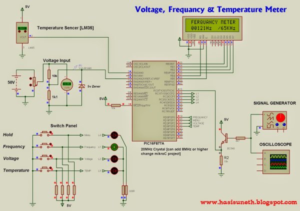
Voltage, Temperature & Frequency Meter With PIC Micro controller

Instructions…

Voltage meter – 

Volt meter can measure dc voltages up to 50v. 5V is the maximum voltage can handle PIC microcontroller, as it is voltage divider (10K,1.1K) use for convert 50V to 5V . 5v zener diode use for safety of PIC microcontroller analog input pin.

Temperature meter – 

Temperature meter can use between 00C to 1500C. But LM35 sensor can use between -550C to 1500C. Sensor’s resistant is changing opposite to temperature, as it is maximum temperature gives maximum voltage output(5v)  and minimum temperature gives minimum voltage output(0v).  

Frequency meter – 

Theoretically, frequency meter can use up to 65KHz, that is because this circuit made by using Timer 1(16bit) of PIC microcontroller.

Voltage, Temperature & Frequency Meter With PIC Micro controller schematicTimer 0 can only measure up to 256Hz, that is because timer 0 is 8 bit timer. Transistor part is use for safety of microcontroller from amplitude of wave signal. This circuit can apply 12v amplitude or more changing transistor base resistor value(4.7K). I tested it, using 12v amplitude square wave signal

Troubleshooting…

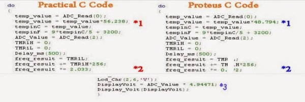
If you have problem about accuracy of voltmeter, temperature meter and frequency meter, you can change values (*1,*2,*3)


For more detail: Voltage, Temperature & Frequency Meter With PIC Micro controller

Current Project / Post can also be found using:

  • tempareture measurement using microcontrolar mini project
  • temperature display device in pic microcontroller
  • temperature measurement project

The post Voltage, Temperature & Frequency Meter With PIC Micro controller appeared first on PIC Microcontroller.

Temperature Indicator using PIC microcontroller

$
0
0

Hi friends, today we will see how to make temperature indicator using PIC microcontroller. The basic aim of this project is make you familiar with PIC microcontroller. It also explains how LM35 and 7 segment displays can be interfaced with PIC microcontroller.

Components required:

Following is a list of components required for temperature indicator using PIC microcontroller – mini project:
Temperature Indicator using PIC microcontroller

  • PIC microcontroller (PIC16F676)
  • 4 digit (or 3digit) seven segment display (Common cathode)
  • Temperature sensor (LM35) IC
  • 5V DC power supply

Circuit diagram:

Following figure shows circuit diagram of temperature indicator using PIC microcontroller.

Theory:

In this mini project we have used PIC microcontroller and a four digit seven segment display is interfaced with it. For sensing the surrounding temperature we have used a temperature sensing IC i.e. LM35. You can use a voltmeter to crosscheck whether the indictor giving correct output or not. The output of the temperature in terms of volts will be in the range of mV.

Temperature Indicator using PIC microcontroller SchematicWorking of LM35:

LM35 is an integrated temperature sensor. It produces output voltage proportional to the temperature. The advantage of using LM35 is that it does not require any external calibration technique and it has accuracy of ±0.4 degree Celsius at room temperature. It draws only 60µA from supply and possesses low self heating. Thus the chances of error get minimized.


For more detail: Temperature Indicator using PIC microcontroller

Current Project / Post can also be found using:

  • temperature measuring instrument for project

The post Temperature Indicator using PIC microcontroller appeared first on PIC Microcontroller.

IR Digital Thermostat for FAN

$
0
0

Introduction

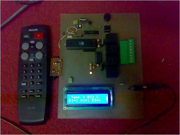
 This circuit measures temperature in Celsius scale and displays it on an alphanumeric LCD screen
When temperature rise to 40 C an alarm is activated and at the same time a relay is also activated which
drives a fan to keep the temperature at a level.
Another feature of this circuit is that you can use the keys “1,2,3,4” of a Philips TV IR remote to turn on or off three relays, The key ‘4’ is used to turn on or off the over temperature alarm.

IR Digital Thermostat for FANHardware

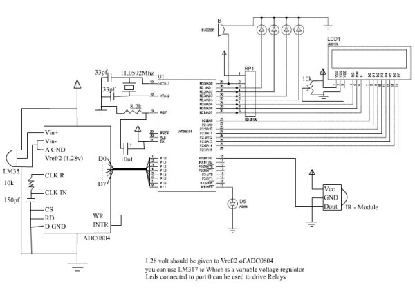
The brain of this circuit is AT89C51 microcontroller. LM35 is a 3 pin chip which is easily available in TO-92
package. LM35 can sense temperature from 0 C to 100 C but it gives analogue output the microcontroller does not understand analogue data, so ADC0804 (analogue to digital converter) is used to convert it to digital form.

This digital data is given to port 1 of microcontroller. (See the circuit diagram) this data is processed by microcontroller and temperature is displayed on lcd connected to port 2.The control pins of lcd are connected to port 0. port 0 also controls the relays and alarm.

The ULN2003 chip is used to drive the relays because the microcontroller pins don’t have enough current to drive them. so relays cant be connected to microcontroller pins directly further more the relays are inductive load and reverse current is generated in them. Pin 1 to 7 are the inputs and 10to 16 are respective outputs. Pin 8 is ground and pin 9 is connected to the output of 7808 voltage regulator.
IR Digital Thermostat for FAN SchematicThe 7805 voltage regulator drives rest of the circuit. I used a standard buzzer driven by LM555 timer/Oscillator chip. The chip is wired as a monostable multivibrator and at its output (i.e. pin no 3) a buzzer is connected.

For more detail: IR Digital Thermostat for FAN

The post IR Digital Thermostat for FAN appeared first on PIC Microcontroller.
Search Results for: Temperature Controlled Fan using 8051 Microcontroller …

$
0
0

Temperature Controlled Fan Report – SlideShare – Temperature controlled fan regulator – electronic circuits, 33 thoughts on “ temperature controlled fan regulator ” siddhu march 12, 2015 at 7:00 am. i didn’t find 100k ptc,5k ptc where are they available and does the. Android controlled robot 8051 microcontroller, Android controlled robot using 8051 and bluetoothour robot expert gaurav khadasane has come up with another innovative way to control a robot. he is controlling his. 8051 microcontroller projects electronics engineering, Edgefx is a top 8051 projects online seller in india. we provide a huge list of microcontroller based projects on 8051 microcontroller with free abstracts..

Search Results for Temperature Controlled Fan using 8051 Microcontroller ... Temperature controlled fan speed – projects 8051, Description: temperature controller can be done by using electronic circuit, microprocessor or microcontroller. now microcontroller is advanced among all above.Temperature based speed control fan microcontroller, Design an automatic temperature control system for smart electric fan using pic.Temperature controlled dc fan – electronic circuits , Description. here is a simple circuit based on two transistors that can be used to control the speed of a 12 v dc fan depending on the temperature.a thermistor (r1.Temperature controlled fan report – slideshare, “temperature controlled fan” a project report submitted by peeyush pashine.

Temperature control system lm35 precision – youtube, One of my 3rd year microcontroller lab projects was to realize a temperature control system using an 8 bit, 80c51 family chip. the schematic contains the.Temperature controlled fan regulator – electronic circuits, 33 thoughts on “ temperature controlled fan regulator ” siddhu march 12, 2015 at 7:00 am. i didn’t find 100k ptc,5k ptc where are they available and does the.
Search Results for Temperature Controlled Fan using 8051 Microcontroller ... Schematic8051 microcontroller projects electronics engineering, Edgefx is a top 8051 projects online seller in india. we provide a huge list of microcontroller based projects on 8051 microcontroller with free abstracts..

For more detail: Search Results for: Temperature Controlled Fan using 8051 Microcontroller …

Current Project / Post can also be found using:

  • temperature measuring using pic
  • list of component temperature indicator microcontroller
  • measurement projects with microcontroller
  • measurment projects by microcontroller

The post Search Results for: Temperature Controlled Fan using 8051 Microcontroller … appeared first on PIC Microcontroller.
Temperature and relative humidity display with adaptive brightness control using PIC12F683

$
0
0

The objective of this project is to illustrate a technique of implementing adaptive brightness control to seven segment LED displays. It consists of a closed loop system that continuously assesses ambient light condition using an inexpensive light-dependent resistor (LDR) and uses that information to adjust the brightness of the display. For the proof of concept, the technique is applied to construct a digital temperature and relative humidity meter that adapts the brightness of the seven segment LED displays to the surrounding lighting conditions.

Temperature display

There are 8 seven segment LED displays used in this project and they are all driven by one MAX7219 chip. The ambient temperature and relative humidity are measured using the DHT11 sensor. The microcontroller used in this project is PIC12F683, which is a low-pin-count (8) device from 8-bit PIC microcontroller family. Auto-adjusting the brightness of the seven-segment LED display with surrounding illumination enhances the readability in all ambient lighting conditions.

Theory and circuit setup

Many smartphones, HDTVs, PDAs, tablets, and computer screens now come with an automatic brightness control that aims to conserve power as well as to make the display easier to see in a broad range of illumination conditions. This feature basically dims the display screen in a dark environment and brightens it when the ambient light level is higher. The brighter screen helps to counteract the effects of glare from ambient light and also takes into account for the decreased sensitivity of human eyes to brightness as the ambient light level increases.

An automatic brightness adjustment is basically a closed loop system that has the capability to assess ambient light and adjust the brightness of the display accordingly. In our project, a general purpose LDR and a fixed value resistor (10K) are connected in series between the power supply and ground pins to create a voltage dividing network, as shown in the circuit diagram below. The resistance of a typical LDR is less than 1 KΩ under bright lighting condition. Its resistance could go up to several hundred KΩ under extremely dark condition. Therefore, the voltage across the 10K resistor increases proportionally with the surrounding illumination. For the given setup, the voltage across the 10K resistor can vary from 0.1V (under dark condition) to over 4.0V (under very bright illumination). The PIC12F683 microcontroller reads this analog voltage through its AN3 (GP4) ADC channel and then sends out appropriate signals to the MAX7219 display driver to adjust the brightness of the seven segment LED displays.

The MAX7219 chip provides a serial interface to drive 7-segment LED displays (common-cathode type) up to 8 digits and requires only 3 I/O pins from microcontroller. Included on the chip are a BCD decoder, multiplex scan circuitry, segment and digit drivers, and an 8×8 static RAM to store the digit values. The segment current for all LEDs is set through only one external resistor connected between the ISET pin and power supply. However, the device also provides a digital control of the display brightness (16 steps from minimum to maximum) through an internal pulse-width modulator. To learn more about the MAX7219 device, read my previous article Serial 4-digit seven-segment LED display. In this project, the GP0, GP1, and GP2 I/O pins of PIC12F683 are used to drive LOAD, DIN, and CLK signal lines of the MAX7219.

In order to measure the temperature and relative humidity, the DHT11 sensor is used. It can measure temperature from 0-50 °C with an accuracy of ±2°C and relative humidity ranging from 20-95% with an accuracy of  ±5%. The sensor provides fully calibrated digital outputs for the two measurements. It has got its own proprietary 1-wire protocol, and therefore, the communication between the sensor and a microcontroller is not possible through a direct interface with any of its peripherals. The protocol must be implemented in the firmware of the MCU with precise timing calculations required by the sensor. I have described more about this sensor and its communication protocol in Measurement of temperature and relative humidity using DHT11 sensor and PIC microcontroller. The PIC12F683 uses the GP5 I/O pin to communicate with the DHT11.

To make prototyping easier, I am using my PIC12F Project board and my Serial 8-digit seven segment LED display in this project.


For more detail: Temperature and relative humidity display with adaptive brightness control using PIC12F683

Current Project / Post can also be found using:

  • pic16f 628 temperature monitor with PTC sensor

The post Temperature and relative humidity display with adaptive brightness control using PIC12F683 appeared first on PIC Microcontroller.

About the Temperature Sensor using pic microcontoller

$
0
0

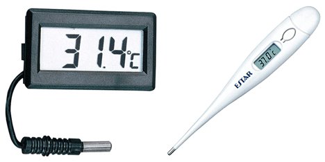
Temperature sensors are used in a wide range of electronic devices, including digital thermometers, home thermostats, ovens, and refrigerators. Figure 1 shows two devices with temperature sensors.

Figure 1. Devices with temperature sensors.

The temperature sensor provided in your kit is a precision analog sensor, whose voltage output is linearly proportional to the temperature. Configured as described here, the sensor has an operating range of about 0°C to +150°C.

About the Temperature SensorConnecting the Temperature Sensor

The temperature sensor is a three-pin integrated circuit. When the device’s flat side is facing towards you, the three pins are labeled 1, 2, and 3, from left to right, as shown in Figure 2.

Depending on your kit, you may have either an LM35 temperature sensor or an LM335 temperature sensor. You can identify your sensor by reading the text on the flat face of the device, as shown in Figure 3. The two sensors are wired slightly differently on the breadboard and produce different analog outputs, so it is critical to identify which type you have before moving ahead.

Figure 3. LM35 (left) and LM335 (right).
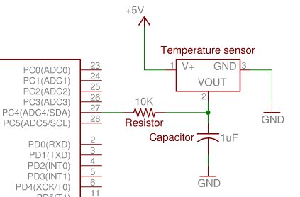
If you have the LM35, connect the temperature sensor as shown in Figure 4. Pin 1 is connected to power, and pin 3 is connected to ground. Pin 2 connects to ground through a 1.0 uF capacitor, and to Port C4 (pin 27) on the microcontroller through a 10K Ohm resistor.
If you have the LM335, connect the temperature sensor as shown in Figure 5. Pin 1 is inserted into the breadboard but not connected to anything. Pin 3 is connected to ground. Pin 2 connects to power through a 1K ohm resistor, and to Port C4 (pin 27) on the microcontroller.

Reading and Plotting Temperature Data

Using MATLAB, it is possible to plot data gathered from the ATmega microcontroller. Using the ms.adc_read command, you can have MATLAB gather data from the temperature sensor and display the temperature over time as an x-y graph.
About the Temperature Sensor1. Send command prompt instructions to read the ADC value from the temperature sensor:

>> data=ms.adc_read(4); %Set data equal to temperature value
>> data %Display the current value for the temperature

2. Write a program in the editor window to plot the data from the temperature sensor:

if exist(‘ms’)   %Remove previous connections
delete(ms)
endms=msci.breadboardkit(‘COM#’)   %Connect to com port
msdefines   %Ensure you have ms objects

for i=1:60   %Start a loop with 60 cycles
pause(1)   %Pause for 1 second

data=ms.adc_read(4)   %Read the analog value
plot(i, data, ‘rs’)   %Plot the iteration and the value
drawnow   %Draw all points plotted so far
hold on   %Keep the same graph on the screen
axis([0 60 0 40])   %Set the x and y axis extentsend

xlabel(‘Time (s)’);   %Label the x axis as Time
ylabel(‘Analog Value’);   %Label the y axis as Analog Value

delete(ms)

Current Project / Post can also be found using:

  • pic based temperature measurement

The post About the Temperature Sensor using pic microcontoller appeared first on PIC Microcontroller.
Humidity and temperature measurements with Sensirion’s SHT1x/SHT7x sensors (Part 1) using pic microcontoller

$
0
0
Temperature and relative humidity are two very important ambient parameters that are directly related to human comfort. Sometimes, you may be able to bear higher temperatures, if there is a lower relative humidity, such as in hot and dry desert-like environment. However, being in a humid place with not very high temperature may make you feel like melting. This is because if there is high relative humidity, sweat from our body will evaporate less into the air and we feel much hotter than the actual temperature. Humidifiers and dehumidifiers help to keep indoor humidity at a comfortable level. Today we will discuss about Sensirion’s SHT series of digital sensors, more specifically SHT11 and SHT75, which are capable of measuring both temperature and relative humidity and provide fully calibrated digital outputs. We will interface both the sensors to PIC18F2550 microcontroller and compare the two sets of  measurements to see the consistency between the two sensors. This tutorial is divided into two parts. The first part will cover all the details regarding the sensors, including their specification, interface, and communication protocol. The second part will be more focussed on the circuit diagram, implementation of the communication protocol with PICMicro, and the results.
Humidity and temperature measurements with Sensirion’s SHT1x SHT7x sensors (Part 1)Theory

Sensirion offers multiple SHT series of digital sensors for measuring both relative humidity and temperature. The temperature is measured using a band-gap sensor, whereas the humidity sensor is capacitive; which means the presence of moisture in air changes the dielectric constant of the material in between the two plates of a parallel-plate capacitor, and hence varies the capacitance. The required signal conditioning, analog-to-digital conversion, and digital interface circuitries are all integrated onto the sensor chip. The various SHT series sensors have different levels of accuracy for humidity and temperature measurements, as described below.

SHT1x are available in surface mount type whereas SHT7x are supplied with four pins which allows easy connection. The SHT11 and SHT75 sensors both provide fully calibrated digital outputs that can be read through a two-wire (SDA for data and SCK for clock) serial interface which looks like I2C but actually it is not compatible with I2C. An external pull-up resistor is required to pull the signal high on the SDA line. However, the SCK line could be driven without any pull-up resistor. The signaling detail of the serial bus is described in the datasheet, which we will implement for PIC18F2550 microcontroller using mikroC pro for PIC compiler. The operating range of both the sensors is 0 to 100% for relative humidity, and -40.0 to 123.8 °C for temperature. The sensor consumes 3 mW power during measurement, and 5 ?W, while in sleep mode.

The SHT11 module that I have got is from mikroElektronika. The sensor (SMD) is soldered on a tiny proto board with all the four pins accessible through a standard 0.1 inch spacing male header. The board comes with pull-up resistors connected to both SDA and SCK lines. One concern in this type of arrangement is the heat dissipated by the pull-up resistors could affect the measurements if the resistors and the sensor are close in the board. We will discuss about this issue later too. The SHT75 module from Sensirion, however, does not include any pull-up resistor for SDA line and therefore must be included externally.

Brief description of SHT1x/7x sensors

Please read the datasheets for SHT1x and SHT7x for detail information about these sensors. I am only providing a brief summary here.

SHT11 and SHT75 are functionally same with SHT75 being more accurate (±1.8% vs ±3%) in measuring relative humidity. Both the sensors can operate from 2.4-5.5 V supply voltage, however the datasheet recommends to use 3.3V for highest accuracy. The default measurement resolution is 14-bit for temperature and 12-bit for relative humidity, which can be reduced to 12- and 8-bit respectively by changing the bit settings of the Status Register (discussed later) inside the sensor chip. We will be using the default resolution settings for measurements.

Humidity and temperature measurements with Sensirion’s SHT1x SHT7x sensors (Part 1)SCK is the clock line that is used to synchronize the communication between the micrcontroller and the sensor. It is an input only pin on the sensor’s side and therefore the microcontroller should be responsible to generate the clock signal. DATA or SDA is a bidirectional data transfer pin for sending data in and out of the sensor. The sensor should receive a conversion command from the microcontroller in order to start measuring temperature or relative humidity. The measurement commands for relative humidity and temperature are 00000101 (05H) and 0000011 (03H), respectively [The first three most-significant bits are actually the address bits, which are always zero for SHT1x and SHT7x sensors, and the remaining 5 bits are the command bits]. Prior to sending a command, a Transmission Start sequence must be issued by the microcontroller which consists of a lowering of the DATA line while SCK is high, followed by a low pulse on SCK and raising the DATA line high again, while the SCK is already high.


Current Project / Post can also be found using:

  • microcontroller based project fit in instrument for temp indication
  • Pic temperature instruments
  • pic16f628 thermo switch
  • temperature measurements without microcontroller

The post Humidity and temperature measurements with Sensirion’s SHT1x/SHT7x sensors (Part 1) using pic microcontoller appeared first on PIC Microcontroller.
Green house intelligent control system

$
0
0

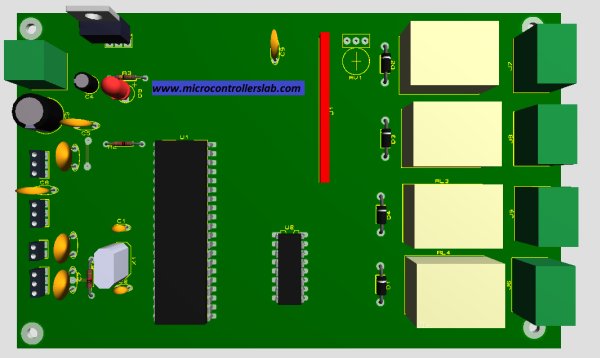
Green house intelligent control system is designed to protect the plants from more cool and hot weather and additional control system is included to save power by making fans and lights automatically turn on and off with the help of intelligent control system. In this project intelligent control system is developed using microcontroller and sensors. Green house system have a very important use now a days in agriculture field.Some plants need specific amount of water for their proper growth and more  productivity, therefore farmer should provide them proper quantity of water. But its difficult for farmer to get estimation for quantity of moisture in soil. But in this project moisture sensor is used to to provide this facility with intelligent control system.Green house intelligent control system

Main functionality of project

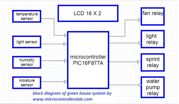
Block diagram below shows the main functionality of green house intelligent control system. Four sensors are used to measure different parameters of green house system which includes temperature sensor, light sensor, humidity sensor, moisture sensor. Four relays are used to control four respective loads as given below:

LM35 Temperature sensor :

When temperature become greater than 25 degree, respective relay become energize to operate fan and when temperature become lower than 20 degree relay  turn off the fan by getting control signals from microcontroller. PIC16F877A microcontroller analog to digital converter module is used to read temperature value and to operate relay which in turn operate fan. To know more about temperature senor and its working, go through following article :

Digital temperature sensor using pic microcontroller

Light sensor :

Light dependent resistor is used as a light sensor. LDR is kind of variable resistor which resistance changes with the change in light intensity. So LDR resistance is converted into intensity of light by using LDR resistance and intensity of light formula. PIC16F877A microcontroller is used to measure intensity of light. When intensity of light fall under a certain limit, microcontroller provide signal to relay to turn on light and when intensity of light raise upto a certain limit , microcontroller provide signal to relay to turn off fan. So light sensor is used to add automatic light switching functionality in green house system, if you don’t have much money to afford a gardener , then you can use green house intelligent control system to make your green house self operating.

HS1101 Humidity sensor :

Humidity sensor is used to check level of moisture in air Because greater or less humidity level in air can also effect growth of plants. Humidity sensor HS1101 is used to measure level of moisture in air. HS1101 is capactive type humidity sensor, So additional circuit is used to convert change in capacitance of humidity sensor into frequency and frequency is measured with the help of microcontroller. Measured frequency is converted back into humidity using algorithm in microcontroller programming. To know more about humidity sensor and its working, I suggest you to go through following article :

Digital humidity sensor using pic microcontroller 

If humisity become grater than a specified limit, microcontroller give signal to respective realy to turn on sprinter which is used to maintain humidity level in air and when humidity level come back to normal limit, microcontroller give signal to respective relay to turn off sprinter.

Moisture sensor :

Moisture sensor is used to measure level in soil. A wire strip is used to measure moisture of soil. Wire strip have a specific resistance at specific moisture, but when moisture increases, resistance of wire strip start decreasing and similarly when moisture decreases, resistance become hire. PIC16F877A used to measure moisture level and to turn on and off water pump with the help of relay.

Simulation :

For simulation purpose I have connected four LED’s instead of real load to check project working and code. LCD is used to display digital values of temperature, light , humidity and moisture. LCD also display the status of devices either they are on or off. As shown in figure below.

Simulation diagram with status of devices :

In simulation I have used variable resistor for wire strip and pulse having different frequencies for humidity sensor.

In above circuit diagrams :

L : for light

S : Sprint

F : for fan

P : for pump

T : for temperature

H : for humidity

M : for moistureGreen house intelligent control system schematich

 Complete circuit diagram :

Complete circuit diagrams of green house intelligent control system and sensors are shown below :

In above schematic of green house system, blue arrow shows connection for senors and back arrow shows relay and lcd connection point.


For more detail: Green house intelligent control system

Current Project / Post can also be found using:

  • how to make working project of temperature measurement and control system
  • ic based metering for temperature measurements rs232

The post Green house intelligent control system appeared first on PIC Microcontroller.
Top PIC Microcontroller Projects Ideas

$
0
0

When we are choosing PIC microcontrollers for projects on electronics or electrical, there are many options for us. Ranging from eight bit to Thirty two bits, diverse micro-controllers are accessible to go well with projects and products of different complications and cost restraints. But if we talk about student projects, it may be either major projects or mini projects; there are only few microcontrollers which are compatible.

Get an idea about some of the top PIC Microcontroller Projects Ideas by reading the following concepts.Top PIC Microcontroller Projects Ideas

Top PIC Microcontroller Projects Ideas:

1. A PIC Sonar (Ultrasonic) Range Finding Project

The PIC micro-controller based sonar range finder functions by spreading a short pulse of noise at a frequency impossible to hear by human ears i.e. ultrasonic sound or ultrasound.  Later the micro-controller notice the echo of the noise spread. The span from spreading noise to echo reception, we’ll estimate the distance from the article. This sonar range project makes use of 5 standard transistors to obtain and spread the ultrasonic sound and a comparator to position the threshold echo recognition level – so there are no unique constituents except the micro-controller. The ultrasonic sound transducers are ordinary 40 kHz sort. Note- the inner oscillator of the PIC microcontroller is employed and this hoards 2 pins – that can be employed for standard I/O.

2. PIC Based BRAM (Beginner’s Robot Autonomous Mobile)

This project exhibits how to develop a BRAM. It is intended to be effortlessly built by bringing into use some of the constituents that can be discovered easily at home. The key controller for this robot project is a Microchip (PIC16F690). 2 old CDs are employed to develop the chassis for the robot system. The geared DC motor, caster, battery power and the robot’s bumper keys or whiskers are grasped in the lower deck while the upper deck comprise of the robot’s sensor board, the PIC16F690 microchip & motor driver.

Below given is BRAM’s construction material:

  • 2 CD or DVDs for the chassis
  • 2 geared DC motor with the wheel or modified servo motor can be used
  • One 3 by 1.5 volt AA battery box with ON-OFF buttons
  • 1 plastic bead and 1 paper clip for the caster
  • 2 micro keys and 2 paper clips for the bumpers sensor
  • Bolts, printed circuit board, Nuts, holders, double tape to embrace all of these constituents together.

3. Versatile Central Heating Program Controller using PIC16F628A

This versatile central heating system controller is intended to make use of a boiler. The 2 relay controls the hot water & heat supply. It contains a front panel key control with a LCD screen of 16×2. It also gives a sequential association that permits to work from distance via PC’s help. The programmer & heating boiler control relays are clutched in different units just to locate the relays near to the boiler whereas the programmer can be positioned anywhere in the residence employing low voltage power back to the relay component. Moreover you can also develop a series interface link neighboring to the programmer in this case only 4 wires for power & relay controls are required.

Features:

  • Self-regulating for central heating and boiler.
  • Ten flexible programs.
  • Programs can be set as per convince.
  • Manual operation and setup from facade panel or remote
  • Battery support for RTC (Real Time Clock).
  • Programmer located at a distance from boiler can use 6-core alarm cable.
  • Front panel can be locked
  • Based on Microchip PIC 16F628 (microcontroller).

4. A Versatile Temperature Data Logger Using PIC12F683 and DS1820

Here we are exhibiting temperature data logger project which is based on a Microchip’s 8-pin micro-controller (PIC12F683). It studies temperature figures from a digital sensor (DS1820) and accumulates in its inner EEPROM. Microcontroller has 256 bytes of domestic EEPROM and the temperature values will be saved in 8-bit format. This implies the 8 vital bits of temperature values from digital sensor will be studied and the temperature resolution will be of one degree C.

Temperature logger features:

  • Interprets temperature from a digital sensor and accumulates in the inner EEPROM
  • Can accumulate approx 254 temperature values. EEPROM location “0” is employed to save the sampling breaks, and location “1” is employed to save the amount of records.
  • 3 sampling break alternatives are there: 1 second, 1 minute, and 10 minute. This can be chosen while powering up.
  • Start and Stop keys for manual control.
  • The recorded values are sent to PC via serial port. A send button is existing to begin data transfer.
  • A LED to show different ongoing processes.
  • Re-set key to delete all previous data.

5. Gas Sensor Using PIC16F84A

Here we are showcasing a gas sensor circuit supported by PIC16F84A microcontroller & GH-312 sensor. GH-312 is capable of sensing gases like liquefied gas, propane, smoke, alcohol, butane, Methane, hydrogen, etc. As it detects any of these gases, it prompts the micro-controller (PIC16F84A), which in return turns ON the buzzer and sparkles the LED. Here we have used 9 volts battery in project as the sensor needs a 9 Volts input. The output of the sensor when it prompts the microcontroller is 5V which is ideal for an undeviating union to any micro-controller. Though 9V battery is used, any 12 volts power supply will labor flawlessly as the sensor can manage from 9 volts to 20 volts and the micro-controller’s voltage is synchronized by a 7805 controller.Top PIC Microcontroller Projects Ideas schematich

6. RS232 Communication with PIC Microcontroller

This project exhibits how to execute a uncomplicated communication through a RS232 interface using a PIC micro-controller. RS232 is a normal for a successive communication interface which permits to transmit and obtain data though 3 wires at-least. By RS232 interface it is achievable to arrange a connection amid a micro-controller and a PC, through PC’s COM port or amid 2 micro-controllers. The RS232 is employed for various reasons such as- transmitting PC commands to a micro-controller, conveying debugging info from a microcontroller to a terminal, download latest firmware to the micro-controller and various other things. PC will be incorporated with terminal program to receive & send data. Data transferred via micro-controller is shown in the terminal window and the key(s) pushed within the terminal will convey the matching key code to the micro-controller.


For more detail: Top PIC Microcontroller Projects Ideas

Current Project / Post can also be found using:

  • pic microcontroller USB programmer
  • peoject on measurement of temperature
  • Temperature display circuit using pic ic pdf

The post Top PIC Microcontroller Projects Ideas appeared first on PIC Microcontroller.


Low power temperature data logger using PIC18F27J53

$
0
0

Design Goals

DIY Friendly – Something that the Make audience could easily build
Improve the reference design – Better measurement resolution, better timing, lower power, non-stop logging
Minimal parts count – Lower cost and shorter build time
Powered by a single 1.5 volt cell (AA, AAA, N or similar) and optional supplementary solar power

PIC18F Dlogger

Parts Selection

One of the design goals is to use the fewest parts need to accomplish the other goals. The reference design uses an EEPROM to store the logged data. The 24AA1025 is a rather expensive part for 128 k bytes of storage. Using a microcontroller with a large internal writeable non-volatile memory may allow this part to be eliminated. That would reduce parts cost and build time. The Microchip parametric parts selector was used to display 8 bit PIC microcontrollers in a 28 pin or smaller package. The displayed list of parts was then sorted by memory size. The highest capacity flash memory shown was 128 k bytes. That is the same capacity as the EEPROM, but some space will be taken by the firmware. The PIC18F27J53 look like a good choice. It is available in a DIP package so the logger can be easily built on solderless breadboard. It also features a real time clock (RTC) that will allow time stamps and a precise sample rate. The analog to digital converter (ADC) is 12 bits – an improvement over the 10 bits of the reference design. It also has USB that could be used to eliminate the need for the FTDI USB to serial cable. The price is 3.23 USD/qty100. The reference design used a PIC at 2.05 USB/qty100 and the 24AA1025 at 2.85/qty100 for a total of 4.90 USD. Cost savings are 1.67 USD. If this where a commercial product, there would be additional cost savings by using a smaller PCB, reduces assembly time and potentially greater reliability (fewer parts to fail.) One possible problem with using the microcontroller’s flash memory for data storage is the write cycle limit. Flash memory can be read constantly, but degrades when it is written. The number of write cycles for the PIC18F..J series parts is 10,000. EEPROMs usually allow 1,000,000 or more write cycles. If one sample is logged every second, it will take about 28 hours to fill 100 k bytes. 10,000 cycles would take more than 30 years, so this is not a problem.

The MCP9700 used in the reference design is a low cost temperature sensor will adequate accuracy. No reason to use a different part.

Storing data in flash memory

The reference design writes each reading to the EEPROM at the time it is read. The EEPROM allows this, but it has to read and write an entire 128 byte page just to update 1 byte. Power consumption could be reduced by buffering 128 bytes to RAM and writing whole pages to the EEPROM.

Flash memory is not as “smart” as EEPROM. It requires that memory written must first be explicitly erased. The flash memory is erased in chunks of 1 k bytes. Writing to flash is done in chunks of 64 bytes. It is not possible to write just one byte. To keep the code simple both erasing and writing will be done in chunks of 1 k bytes. 1000 readings will be accumulated in RAM. After the 1000th reading, they will all be written to flash along with up to 24 bytes of metadata. The metadata includes the real time stamp of the first reading and the absolute value of the first reading.

102 k bytes of flash are needed to store 100,000 readings. 100 k bytes will contain logged data. 1 k bytes will always be erased – this separates the head and tail of the circular buffer. The highest 1 k of flash is not used because the top 8 bytes contain the config words. It is easier to just ignore this last 1 k than to make exceptions for it. The total flash size is 128 k, so 26 k is available for the firmware.

When highest block of flash has been used, the buffer will wrap around back to the first block. The flash will always contain the latest 100,000 readings.

The next block to be used will be erased before the current block is written with the data collected in RAM. This ensures that there will always be an erased block between the head and tail of the circular buffer. If the erase fails, then the previously erased block will remain.

The plot below is the first dataset from the logger. Excel can not handle 100,000 rows, so only the first reading of each block of 1000 is plotted.

Data transfer

The Ymodem protocol is used to reliably transfer the logged data in binary form. This protocol is quite old and still well supported. It uses a 16 bit CRC to detect transmission errors and can handle text or binary data. Downloading the logged data is simply a matter of using terminal software to initiate a Ymodem download. A 101 k byte file named ‘datalog.bin’ will be downloaded in about 1 minute. The entire 101 k is transferred even if only part of it contains logged data. Logging does not stop during download.

Preventing data resolution loss

The reference design converts the ADC reading to degrees C and stores that in the EEPROM. This results in a loss of resolution. A temperature of 23.4 will be stored as 23 – an unnecessary error of 0.4. If a steady slow change in temperature where plotted, it would be jagged line rather than a smooth line. Storing the actual ADC reading will preserve the full resolution of the measurement. It can be converted to whatever unit of measure is desired with whatever resolution is needed. Using the logger for something other than temperature would not require any firmware changes. Storing all 10 or 12 bits from the ADC would require more space than storing the scaled value as an integer. If the ADC reading changes by a small amount from one reading to the next, then the change in value can be stored rather than the absolute value. Eight bits will allow changes of -128 to +127 between each reading. The code is written to propagate any overflow error to the next reading. For example a change of +200 would be encoded as +127 and the error of +73 would be added to the next sample. This may result in an occasional incorrect reading, but the sequence will correct itself. It is effectively a low pass filter.


For more detail: Low power temperature data logger using PIC18F27J53

The post Low power temperature data logger using PIC18F27J53 appeared first on PIC Microcontroller.

Automatic Temperature Control System using PIC Microcontroller – XC8

$
0
0

An automatic temperature control system has the ability to monitor and control the temperature of a specified space without human intervention. The primary purpose is to manage the temperature of a given area based on settings by a user of the system.Automatic Temperature Control System using PIC Microcontroller XC8

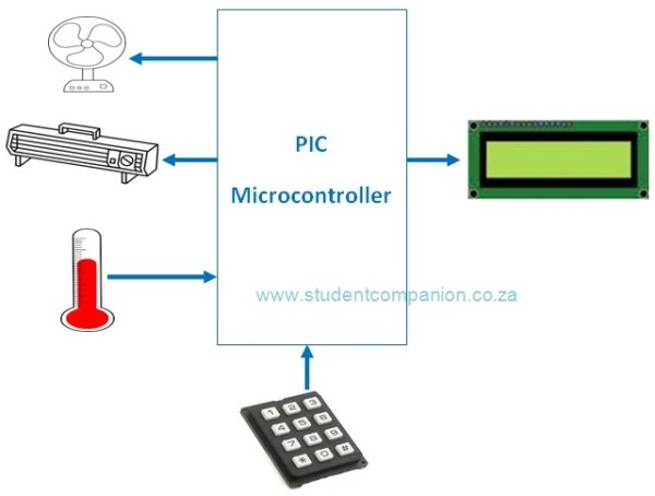
This project uses a PIC microcontroller to automatically control the temperature of an area. This area could be a small plant, a house or any place or device that require a controlled temperature like an incubator (egg) for example. Figure 1 shows the block diagram of the system to be designed. The desired temperature setting is entered using a keypad. The temperature of the area is measured using an analog temperature sensor, the LM35 precision integrated-circuit temperature sensor is used for this.

The microcontroller reads the temperature every 10 s and compares it with the desired value. If the desired value is higher than the measured value, then the heater is turned ON to heat the area. The heater is switched OFF once the desired temperature is reached. If on the other hand the measured value is higher than the desired value, then the fan is switched ON to cool off the area until the required temperature is reached. An LCD display shows the measured temperature continuously.

Figure 2 shows the circuit diagram of the project. The LCD is connected to PORTB. The LM35 precision analog temperature sensor chip is connected to the analog input pin AN0 (RA0). A 3×4 keypad is connected to PORTC. The ‘*‘ key of the keypad is used to clear the value entered during the temperature setup and the ‘#‘ key is used to ENTER (save) the setting. The heater and the fan are controlled using transistors and relays connected to pins RA1 and RA2 of the microcontroller respectively.Automatic Temperature Control System using PIC Microcontroller XC8 schematich

Note: The Terminals ratings of the relay should depend on the power of the Heater and the Fan. If you decide to use 220V Heater and Fan, use appropriate relays which can handle that voltage and current. The low voltage DC of the coil should be preferably 5V and with low current for the BC108 transistor to handle. Please observe the safety precaution as 220V is dangerous.


For more detail: Automatic Temperature Control System using PIC Microcontroller – XC8

Current Project / Post can also be found using:

  • temperature measurement project for students

The post Automatic Temperature Control System using PIC Microcontroller – XC8 appeared first on PIC Microcontroller.
Low cost temperature data logger using PIC and Processing

$
0
0

This project describes an easy and inexpensive way of adding a digital thermometer and data logging feature to a PC. It involves a PIC microcontroller that gets the surrounding temperature information from the Microchip MCP9701 sensor, and sends it to a PC through an USB-UART interface. The USB port of the PC is also used to power the device. The open-source Processing programming platform is used to develop a PC application that displays the temperature in a graphics window on the computer screen. The PC application also records the temperature samples plus date and time stamps on an ASCII file.Low cost temperature data logger using PIC and Processing

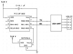
This project is based on Microchip’s PIC12F1822 microcontroller from the enhanced mid-range PIC family. It has got 8-pins in total and the power supply voltage range of 1.8V to 5.5V. The microcontroller has four 10-bit ADC channels and one Enhanced Universal Synchronous Asynchronous Receiver Transmitter (EUSART) module for serial communication. The temperature sensor used here is MCP9701A, which is a Low-Power Linear Active Thermistor IC from Microchip Technology. The range of temperature measurement is from -40°C to +125°C. The output voltage of the sensor is directly proportional to the measured temperature and is calibrated to a slope of 19.53mV/°C. It has a DC offset of 400mV, which corresponds to 0°C. The offset allows reading negative temperatures without the need for a negative supply. The output of the sensor is fed to one of the ADC channels of the PIC12F1822 microcontroller for A/D conversion. The internal fixed voltage reference (FVR) module is configured to generate a stable 2.048 V reference voltage for A/D conversion. The use of FVR module ensures the accuracy of the A/D conversion even when the supply voltage is not stable. The PIC12F1822 microcontroller then serially transmits the 10-bit ADC output to a PC.Low cost temperature data logger using PIC and Processing schematich

The circuit diagram of this project is pretty simple. The microcontroller reads the temperature sensor’s output through RA2/AN2 pin and convert it to a 10-bit digital number. The Tx (RA0) and Rx (RA1) port of the EUSART module are connected to the corresponding pins of the USB-UART module.


For more detail: Low cost temperature data logger using PIC and Processing

The post Low cost temperature data logger using PIC and Processing appeared first on PIC Microcontroller.
DS18S20 Dual Temperature Meter using pic microcontroller

$
0
0
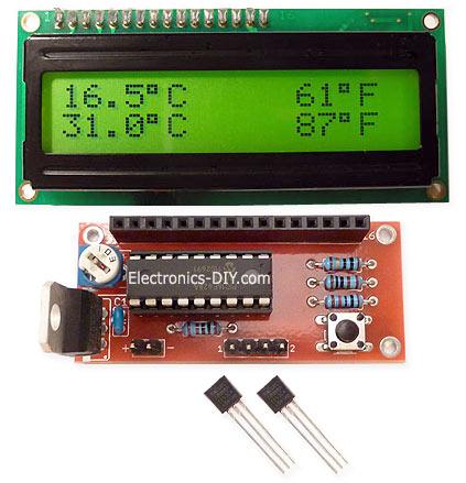
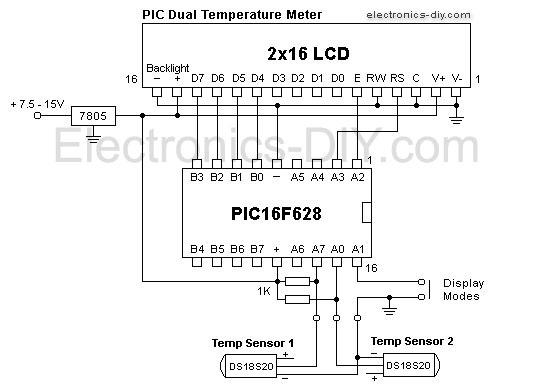
 DS18S20 Dual Temperature Meter Component List:
1x 2×16 LCD with Backlight
1x 16×1 LCD Female Header Connector
1x 16×1 LCD Male Header Connector
1x Programmed PIC16F628
2x DS18S20 1-Wire Digital Temperature Sensor
1x 100nF Capacitor
1x 10K Pot (LCD Contrast)
1x 10K Resistor
2x 1K Resistor
1x 10 Resistor
1x LM7805 Voltage Regulator
1x Tactile Switch (Display Modes)
1x 2-PIN Male Header Connector
1x 4-PIN Male Header Connector
  Technical Specifications:
Temperature Measurement:
-55 to 125°C (-67 to 257°F)
Accuracy: 0.5 °C / 1 °F
Supply Voltage: 7.5 – 15V
Power Consumption: 8mA (when LCD backlight is turned off)


DS18S20 Dual Temperature MeterDS18S20 Dual Temperature Meter

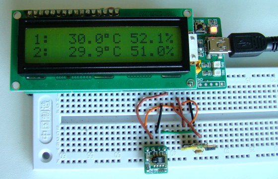
This is a simple to build DS18S20 dual temperature meter that allows to measure temperature in two different locations at the same time. The meter is built with very few components thanks to the use of PIC16F628 microcontroller and 2×16 character LCD display. It is like a small computer that can be customizable by upgrading its hex firmware.

DS18S20 dual temperature meter uses two very exciting DS18S20 digital temperature sensors that come in convenient TO92 package. Unlike regular sensors where temperature readings are passed as varying voltage, DS18S20 passes temperature information in a digital format as data. This brings many new possibilities and enables to pass temperature information over much longer distances just over a two wire cable. With this capability temperature can be measured in different locations at the same time away from the main circuit board. With regular temperature sensors that rely on the voltage cables must be as short as possible because longer wire lengths introduce stray resistance and bring unreliable readings.

Another great feature of DS18S20 sensor is that it doesn’t require any calibration at all, while providing 100% accuracy out of the box. That means that you just plug it in and there’s no need spending time recalibrating temperature readings. This is all due thanks to the nature of sending information in a digital format. In fact DS18S20 is just like a computer connected to the network that has a unique serial number identifier similar to an IP address.

DS18S20 Dual Temperature MeterMultiple DS18S20 sensors can send information simultaneously, even over the same two wire bus cable. The two wires provide 3-5V voltage supply to the sensors and they are also used to pass data in two different directions. If wires are very long so that voltage on DS18S20 sensors drops below 3V external 5V voltage supply can be used with 1K resistor to power the sensors.

Once PIC microcontroller receives temperature information it converts it into both Celsius and Fahrenheit values so that they can be displayed on LCD display. DS18S20 dual temperature meter is capable of measuring temperatures from -55 to 125 °C degrees Celsius (-67 to 257 °F Fahrenheit) with 0.5 °C / 1 °F accuracy. If you just need to measure temperature in one location you may just use one DS18S20 sensor and PIC16F628 microcontroller will use just one sensor.

For more detail: DS18S20 Dual Temperature Meter

The post DS18S20 Dual Temperature Meter using pic microcontroller appeared first on PIC Microcontroller.
12F675 Tutorial 5 : A Temperature data logger using PIC EEPROM. using pic microcontroller

$
0
0

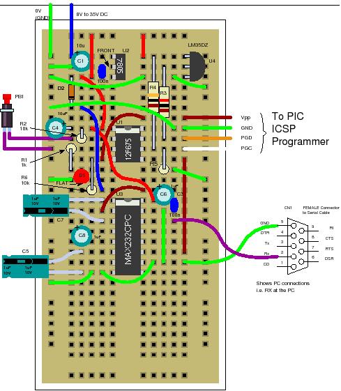
EEPROM is useful for storing long term data such as data logger information and this PIC microcontroller EEPROM project saves the temperature from an LM35DZ IC to the PIC’s internal long term data storage area.  The project follows on from the last project using the virtually the same hardware.
It stores temperature readings internally at regular intervals until full and after this it turns on the LED. The LED is really just for showing that something is happening and in a real data logger you would not use it.
12F675 Tutorial 5 A Temperature  data logger using PIC EEPROM.Jump to Solderless breadboard.
Jump to Circuit Diagram.
Jump to Software.

Note: This project is not optimized for power consumption so the best way to use it is powered from a power block.  The current consumed is about 13mA (LED off) 16mA (LED on at end). If you want to use a battery use a rechargeable PP3 and do not attach the LED.

The 12F675 may not the best PIC microcontroller to use for low power data logging and a better choice would be the 16F88 as it can change its internal oscillator on the fly going into slow (current saving) mode.  But you could use the 12F675 with a slow external 32kHz crystal. 

At every ADC reading the LED is flashed briefly and when you select a 500ms reading interval you can see the readings being taken.  When 64 readings are accumulated the LED is lit permanently – showing that the data store is full.


Note: For this chip you only get to store 64 results as you need to store an unsigned integer for every ADC result and this takes 2 bytes so 128 Bytes/2  = 64 results.
You can hit the button at any time and the contents of the EEPROM will be read from the internal EEPROM and transmitted to the PC via the serial port.

To erase the internal EEPROM hold the button and cycle the power – this flashes the led 6 times indicating erase (normal startup flashes the LED 3 times).

Solderless breadboard

The solderless breadboard and circuit diagram are nearly the same as used in the previous project so if you have already built it you don’t need to do any more.  Just add the blue wire, D2 and R6.

12F675 Tutorial 5 A Temperature  data logger using PIC EEPROM.

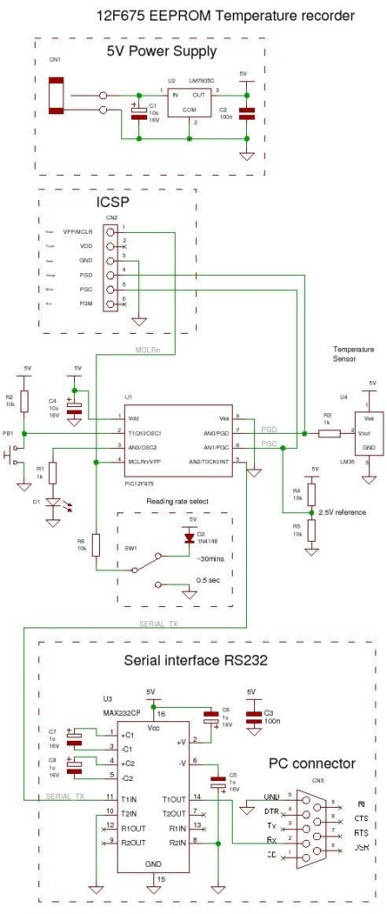
Circuit diagram

Note that the switch shown below is just a blue wire above. Either leave the  blue wire where it is to hold the input, at pin 4, high or move the top of the blue wire to ground (0V – green wires at top left – on the left of the solderless breadboard) to set GP3 (pin 4) low.

Note: The diode stops the programming voltage conflicting with the 5V power supply – reversed biased when the high programming voltage is present.


For more detail: 12F675 Tutorial 5 : A Temperature  data logger using PIC EEPROM.

The post 12F675 Tutorial 5 : A Temperature data logger using PIC EEPROM. using pic microcontroller appeared first on PIC Microcontroller.

Viewing all 121 articles
Browse latest View live


<script src="https://jsc.adskeeper.com/r/s/rssing.com.1596347.js" async> </script>