Quantcast
Channel: Temperature Measurement Projects - PIC Microcontroller
Viewing all 121 articles
Browse latest View live

SKIN TEMPERATURE MEASUREMENT

$
0
0

Abstract:

This report represents the design and implementation of a skin temperature measurement system. The system aims to measure the skin temperature from a sensor and send it to the PC using a USB cable to display on screen. The data needs to be updated every second.
The PIC18F4550 microcontroller has been used in this project to obtain data from the sensor and send it to the PC using USB 2.0 that has been built into the microcontroller. The microcontroller has a 10-bit Analog Digital Converting accuracy that is one of the important criteria for this design as it is going to be used for medical purposes. As the project concentrates more on designing software than hardware, the EasyPIC4 development board was used which comes with all hardware required for this project. The Michel Jackson diagram method was used to design and implement the coding program for the microcontroller software part of the system. The MikroC IDE has been used to compile and load the program into PIC18F4550 microcontroller. The program for the microcontroller uses C language that aims to keep the USB link alive by using interrupt function. A sensor collects data from sensor as 4 bits and send it to the PC every second using a USB cable.
The data received from sensor, will be sent by microcontroller to the PC. The Visual Basic software was used in the PC side of device to catch and output the data on the screen. A template file for the Visual Basic program was generated by Easy HID wizard to make software programming part easier for designer. The template file was modified in such way that can operate following activities for a user purpose:  A message that indicates if USB connector is plugged or unplugged from the PC.  Different techniques to display data on screen (textbox & progress bar). Button control key to end and exit from program.  Finally labeling the Form as well as display and control for user attention. The USBTrace analyzer has been used in the scenario any problems occur during or after the design and construction of the software. The software enables a user to monitor the data on the USB bus that sends the data to the PC from microcontroller.

Introduction:

There are different techniques used to send a data from a sensor to a PC for further operation and outputting results. A requirement of the project is that the customer needs an easy to use serial cable for transferring the data from a skin temperature sensor to the host computer.
Any data communication from peripheral device to a host computer by a cable can be divided into two main groups serial and parallel data transfer. In a parallel communication, group of data will transfer simultaneously on more than one communication lines while in a serial communication the data transfers one bit at a time on single communication line. This means the ability of data transferring at each given time in the parallel communication is greater than the serial communication which makes the device faster.
There are a number of advantages of using a serial port over a parallel port such as:
The serial ports are smaller as they have a single line to transfer therefore fewer pins compare with the parallel port needed.
Less EMI and interference compare with the parallel port which has many wires switching over each other all the time.
Less time for error correction compare with the parallel ports that have many lines to transfer the synchronized data.
Finally the serial port is easy to connect compare with parallel port.
Universal Serial Bus (USB) is an external serial interface to transfer data from one electronics device to another using a USB cable. The USB is a set of connectivity specification was developed early 1996 by Intel to establish communication between a peripheral device and a host computer which uses a serial stream. The USB cable provides a high speed, easy connectivity and automatic configuration when it is plug in. The first USB specification was developed was a USB 1.1 that had up to 12Mbps data transfer rate. However in April 2000 the USB 2.0specification was released that had speed of up to 480Mbps which was 40 times greater than the USB 1.1.

In this project the USB 2.0 has been used to transfer data from the peripheral devices (temperature sensor device) to the host computer by USB cable.
There are a number of advantages that make companies to design their product to use the USB 2.0 instead of a serial or parallel port, more details of the USB 2.0 and some of its advantages are mentioned in following: Easy to use for the user as it has a plug and play function that means the user can connect any device to the PC without rebooting the system. Fast enough to avoid a communication bottleneck, latest standard by up to 480Mbit/sec data transfer rate. A standard PCs comes with 2 or 4 USB ports fit in, it will enable a user to connect up to 127 devices to the PC using the USB hubs. The size of a USB port is quit smaller and it is easy to connect compared to other types. Using the USB 2.0 gives more control to the user to control the device using its PC as it has two ways communication. Low cost and power consumption from the PC.
Is it not sounding old? The answer is obviously „yes‟. Technology is always progressing. It pays to move forward with new technology than try to employ the old or current. However USB 2.0 technology is widely popular and has become a standard requirement in PCs hence will be around for some time to come.
In this report convenient and up-to-date techniques and technology have been used in order to use the USB 2.0 cable for the system that enable the user to achieve their goal to satisfy their customer. After some research over the technologies that are available in the market to convert an input data to 10 bit digital data and the chips that uses USB 2.0 technology to respond to different events on the bus, various chips were found that required a range of firmware support in order to establish USB communication.

The PIC18F4550 microcontroller was chosen to be suitable solution for this project as it satisfies the specification as it has both technologies required for this project built in (10bit A/D conversion, USB2.0) as well as providing more flexibility, reliability and future modification to the design.

2)  Aim and Objectives:

2.1. Aim:

The aim of this project is to design a system that can measure skin temperature by an analog temperature sensor and screen out the result on a PC‟s screen every second.

2.2. Objectives:

Objectives for the system can be broken down to the following objective: 1. The primary objective of this project is to use a serial data transfer cable. 2. Secondary objective is to have good data accuracy for the system. 3. Third obj

ective is to make more flexibility and compatibility for the system for future modification. 4. Final objective is to use an easy to understand and up to date technique to output the data on screen.

2.3. Specification:

1. Using the serial data transfer techniques (USB 2.0 Technology) as the customer wants it to use as an On-The-Go device. 2. Accuracy of minimum 8-bit to convert an analog input signal to corresponding digital number. A

s the device designed to be use for medical purposes to diagnose the skin diseases. 3. Updating the reading data from the sensor every one second. It is more accurate to get average from token results as the reading is not stable. 4. Display the input data on the screen. Use simple and easy to use technique to display the data for the user.

2.4. Deliverable:

The project outcome will be as follows: A working model of the Skin Temperature Measurement system. (Hardware) The software required to produce the behaviors specified. (Software) Research for upgrades and add-ons for the system i.e. software and hardware. Interim and final project documentation. Software and hardware testing.

3) Technical background and context (hardware/software):

3.1. Hardware:

1) Easypic4 Development Board 2) PIC18F4550

3.2. Software:

1) MikroC Compiler for PIC 2) PICFlash2.0 with mikroICD 3) USBTrace USB protocol analyzer 4) Microsoft Visual Basic 6.0 5) Easy HID USB wizard

4) Technical Approach:

The first plan of action was to study the customer‟s requirements, specifications and to identify key factors of the project. The next step was to obtain information from journals and the Internet to acquire information on how existing systems with serial ports work and to investigate what current technologies are in place that gather data from skin temperature sensors and communicate in similar fashion with a PC using USB technology.
After enough research on technologies available, the following hardware & software parts have been chosen, that are suitable for the project in order to meet the required specification set at the start of project which satisfies the criteria:

1. Hardware:

The hardware component of the project can break down to two main components:

1.1-PIC18F4550 Microcontroller:

The PIC18F4550 Microcontroller has the following features: The main feature of this microcontroller is that it has built in the USB 2.0 interface.  Low power consumption (nano Watt Technology)  Enhance Flash program and large amount of RAM memory for buffering (1Kbyte Dual Access RAM for USB)  Has different pin layout (40 and 44 pins) High Performance and speed up to 12Mb/s in Full speed mode and 1.5Mb/s in low speed mode. Accuracy of 10-bit to convert analog signal to digital number relatively. Up to 13 analog to digital converter model channels with programmable accusation time.

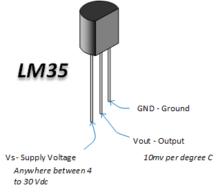
The project uses the 40 pins chip shown in figure(1) as it was compatible with development board provided by university lab (EasyPIC4) that has all features that satisfy the project needs.

PIC18F4550 Microcontroller

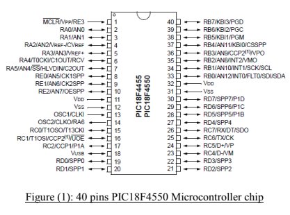
In this part of the report more details of some features and functions of PIC18F4550 that will be needed to use later on for the project will be given in following:

USB Bus Interface:

The microcontroller supports USB interface to communicate with a host computer directly. It can transfer data with a full speed (12Mb/s) or low speed (1.5Mb/s) that allows fast communication between the device and a PC.
Figure (2) shows the infrastructure of the USB section of PIC18F4550 that use Pin23 (RC4) and Pin24 (RC5) for USB interface. RC4 is used to indicate the D- data pin and RC5 uses to indicate the D+ data pin. These pins are connected internally to two pull up resistors that can select full speed operation by connecting the resistor to the D+ data pin and low speed by simply connecting the resistor to the D- data pin.

The register UPUEN is use internally to activate and deactivate the pull up resistors. For disabling resistors simply configure UPUEN= 0x00 and vice versa to enable them the UPUEN register has to be assigned to 0xff. These resistors can be connected externally as shown in figure but in the case of the external resistors, they can be disabled and enabled manually by connecting the resistors to 3.3 volts supply, but the user has to make sure to disable the internal resistors in the scenario of where the external resistors are to be used.
Three control registers are managing operation of the USB interface internally and 22 register are being use to manage the actual USB transaction. But MikroC language has a USB library function that can be used in order to implement the USB transaction. However there is no need to configure these registers in this project.

USB Bus Interface

10bit analog to digital converter module:

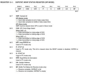
The analog to digital converter module has 13 Input/output pins for the microcontroller with 40 pins that has been used for the project as it was mentioned before these pins provide up to 10-bit analog signal to digital number accuracy. The module has five registers:  A/D Result High Register (ADRESH)  A/D Result Low Register (ADRESL)  A/D Control Register 0 (ADCON0): To control operation of analog to digital module.  A/D Control Register 1 (ADCON1): To control function of port pins.

10bit analog to digital converter module
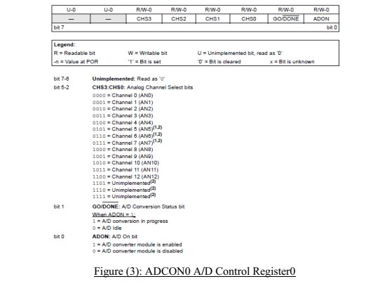
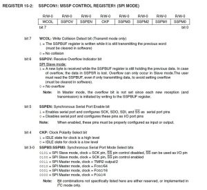
A/D Control Register 2 (ADCON2): To configure the A/D clock source, programmed accusation time and justification. Figure (3) shows the actual register configuration in order to operate in such way which can take analog signal from channel0. In Figure (3) the ADCON0 was assigned to zero to select channel 0 as an analog input.

10bit analog to digital converter module

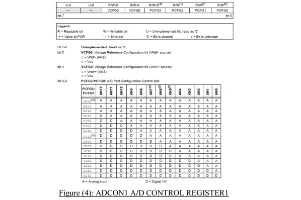
In Figure (4) the ADCON1 register was assigned to zero to set all channels to analog.

channels to analog

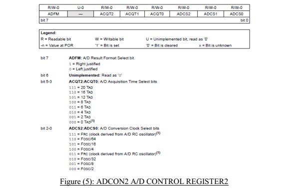
In Figure (5) the ADCON2 was assigned to 0xA6 to set the Ref=+5Vand A/D clock = Fosc/64, 8TAD in this project.

Input/ output ports:

There are up to five ports (PORTA, B, C, D, E) are available for the PIC18F4550 microcontroller. Each port can be used as an either input or output for other peripheral features on the device. Each port has three registers to control operation which has to initialize and activated before it can be use. The following shows the operation of these port‟s registers:
TRIS register is use to specify direction of data.  PORT register that reads the pin level of device. LAT register that latch the output or read and modify and write operations on the value of I/O pin.
It is better to select the PORTA as an analog input as several of its pins multiplexed with an analog inputs. PORTA is an 8-bit wide and bidirectional. To set PORTA as an input pins, the TRISA has to be set to 1. PORTB is an 8-bit wide and bidirectional which is going to be use as an output port by setting TRISB to 0.

Interrupts:

In general interrupt is a signal that indicates attention or change in execution in programming. In this case the processor saves its states and check interrupt vector address that give the address of Interrupt Service Routine (ISR), at this point the processor will execute the ISR where the instruction for this interrupt has been stored. After the processor finishes executing of the ISR instructions, it will go back to the main program and continue from where it is left of by checking its state. The PIC18F4550 microcontroller has two interrupt sources and a priority feature that allow each of the interrupt sources to get assigned to high priority that is located in 000008 interrupt vectors and low priority that is located in 000018 interrupt vectors.
From the name of priority can recognize that each high priority interrupt should be able to interrupt the low priority interrupt which is in the progress.

The 10 registers used to control interrupt operation has been listed as follows:  RCON  INTCON INTCON2  INTCON3  PIR1, PIR2  PIE1, PIE2  IPR1, IPR2 However there is no need to set all register for any interrupt operation. Three bits are controlling interrupt source operation: 1. Flag bit: This bit is indicated when interrupt events have occurred. 2. Enable bit: This bit allows the program that is being executing to link to the vector address in the case of flag bit is set. 3. Priority bit: This bit use to select a high priority from a low priority.
As the project contains of the interrupt operation to keep the USB function alive, there is no need to set some of the registers as well as the interrupt bits. And Timer0 function will be use as an overflow function to produce the 0.832ms delay we need before sending the keep “alive” messages.
In this part there is a need to set the registers that we need in order to disable and enable interrupt function. Before any interrupt operation is to be used it is better to disable all the interrupts in the system and this can be done by setting the Figure (6) register:

Interrupts

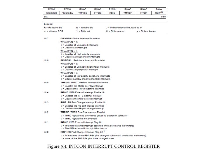
By setting INTCON = 0X00 we can disable all the interrupts as shown in Figure (6). The next step is to set INTCON2 = 0xF5 that set Time0 overflow and RB port as high priority and disable all the PORTB pull ups and set all the interrupt on the rising edge.
After that the INTCON3 has to be set to 0xC0 that enable the interrupt and set it as a high priority. The rest of register can be set to zero as they disable the functions.
Finally the interrupt has to be enabled where it will be used, this will be done simply by setting INTCON register to 0xE0 that enable the Timer0 overflow interrupt and all the high priority interrupts as shown in figure above.

Timer0:

Timer0 can be using as either a timer or a counter in this project it has been used timer0 as an interrupt overflow, it is incremented on every clock by default. Here the timer0 will be used to re-enabling the USB function every 0.832ms, this achieved by setting the following register to the calculated prescale value shown in following: The timer0 can be set to the 256 pre-scale values and the 8 bit mode. However crystal frequency is 8MHz but the CPU is set to operate in 48MHz clock this setting will be described later. Selecting timer value of 100 (TMR0L=100) with clock frequency of 48MHz gives the timer interrupt interval of 0.832ms that calculated below: T=1/f → T=1/48M=0.02083us (256-100)×256×0.02083us= 0.832ms The timer0 register T0CON uses to control the all aspect. After looking at the register instruction and previous knowledge of setting, the T0CON should be set to 0x47in order to enable the timer0 and set all the bits to what it needs to be as shown below.

Circuit Diagram:

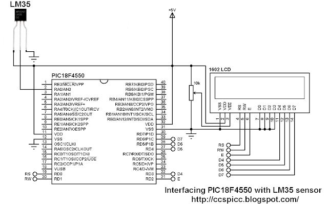
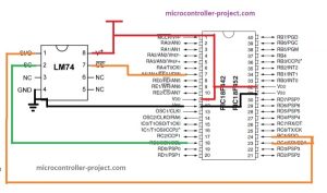
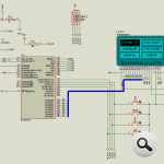
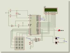
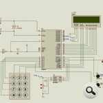
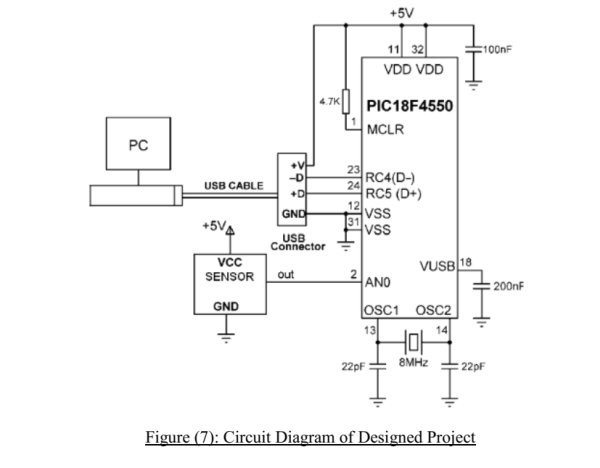
After getting all this information about PIC18F4550, The actual hardware connection between the microcontroller and the host computer has been designed and shown in Figure (7).
The designed circuit diagram shows a sensor who is connected to channel0 (AN0) of the microcontroller. The USB cable is used to connect USB connector to the host computer. The USB connector connection was established by connecting D- to port pin RC4 and D+ to port pin RC5 of USB cable. The microcontroller clock is operating on 8MHz crystal and reference voltage was 0 – 5 volts.

Circuit Diagram

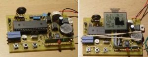
1.2-EasyPIC4  Development Board:

EasyPIC Development board was designed and built by the MikroElectronica to use for the Microcontrollers with 40 pins layout. The board was recommended and provided with the university and it was familiar for me as it was used for other project previously.
The board has all the hardware features that needed for this project, therefore there is no need to design and build the hardware that leaves more time for designer to spend on the software part of the project.
In order to activate the hardware parts of development board that is needed for the project. The following setting and connectivity has to be established by the user. In this section more detail of the hardware parts of EasyPIC4 board and how to set the parts in order to operate as expected given in Figure (8):

EasyPIC4 Development Board

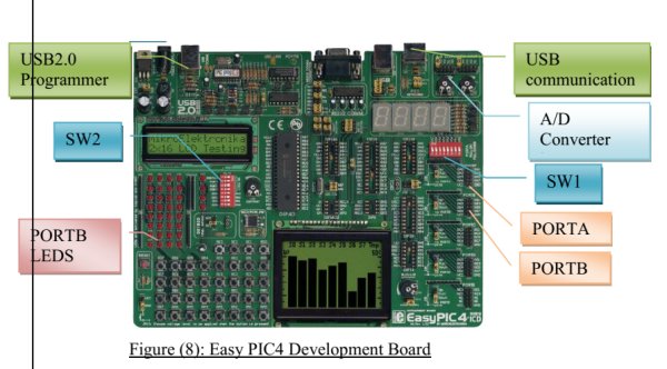
The hardware components used in this project have been indicated in Figure (8) and their settings have been described in following:
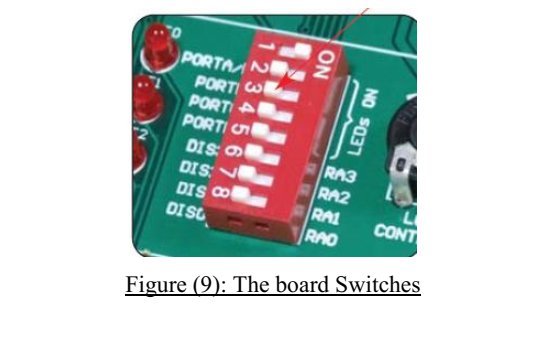
Switches:

The board has two sets of switches (SW1&SW2) that have two positions (ON&OFF) which activate and deactivate the connection. First sets of switches (SW1) are used to enable connection between the microcontroller and the input ports as well as the external pull up/down resistors. In order to avoid effect on the input port voltage level these resistor should be disabled. In this project it is better to leave all the switches OFF as the analog input is going to be measured. The next sets of the switches (SW2) are used to enable the LEDs connected to the PORTs. In this project the PORTB is enabled by placing the switch in the ON position and leave the rest of the other ports in the OFF.
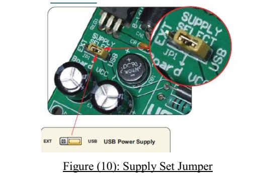
Switches

Power Supply:

The board can be powered up by either regulated power from the USB cable or by the external power supply. In the case of using regulated power from the USB programmer cable the power will be supply while the board connected to the PC bye the cable. In this case jumper JP1 should be set to the right hand position as shown in Figure (10):
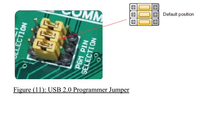
Power Supply

USB 2.0 Programmer:

In order to use this port, the PICFlash2 programmer software which comes with the board or will be provided on the Microchip website which has to be downloaded and installed onto the PC. This software enables the user to load a program into microcontroller. There is no need to reset the microcontroller as programmer will reset it automatically. There is one jumper (JP5) located for this part that should be set as a default position.

USB 2.0 Programmer

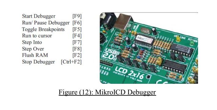
MikroICD Real Time Hardware in Circuit Debugger:

MikroICD Debugger is a tool that enables the user for Real Time debugging on hardware. MikroICD programmer provides a service for the user to check the program variable values while the program running on the microcontroller using a Special Function Register (SFR) and EPPRAM. This tool can be used through MikroC compiler, it can communicate with the compiler and supports common debugger commands that shown in Figure (12).
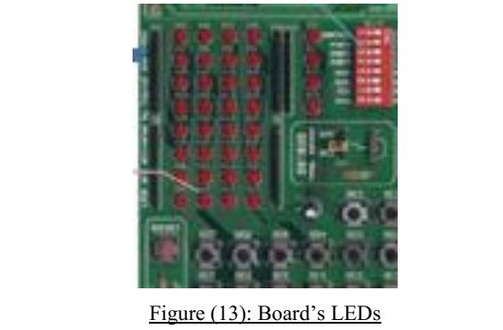
MikroICD Real Time Hardware in Circuit Debugger

LEDs:

Light Emitting Diodes (LEDs) will be used commonly on the board to display output. The board contains of the 36 LEDs of which 8 LEDs are used for each the PORTA, B, C, and D except PORTE that has 4 LEDs. In this project PORTB was selected as an output by changing the position of SW2 to ON position, and monitor output value all the time while the program was tested.
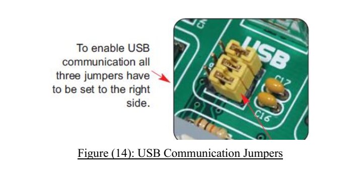
LEDs

USB Communication:

This USB connector can communicate with those microcontrollers that have the USB technology built in such as the PIC18F4550 microcontroller. To enable communication between the microcontroller and connector the jumper set group has to set to the right position that disconnect the pins RC3, RC4 and RC5 from the rest of the system and connect it to the USB connector.

USB Communication

A/D Converter Input:

The board has two potentiometers built in which can work with an Analog Digital Converter (ADC) to produce the input range of 0 to 5 volts. These potentiometers can be used for testing purposes in the case of unknown sensor is going to be used.
In this project these potentiometers have been used as the customer did not provide any details of sensors that are going to be used as two analog signals were presented by these potentiometers in the same time.
To connect these two potentiometers the following connection has to be established. The jumpers group JP15 can enable connection between P1 and one of the following pins: RA0, RA1, RA2, RA3 and RA4. The jumper group JP16 can enable connection between P2 and one of following pins: RA1, RA2, RA3, RA4 and RA5. In this project the jumper JP15 has to be connected between P1 and pin RA0.

A D Converter Input

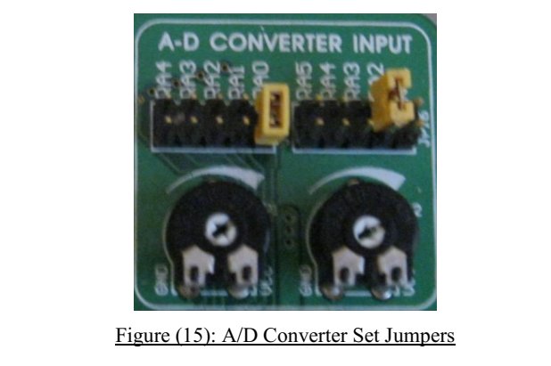
The corresponding switch (SW1) has to be in the OFF position that disconnect the Pull up/down resistor from PORTA of the circuit, this gives measurement result without any interference.

Direct Port Access:

There are five direct ports were provided on the board to enable the user to connect to any peripheral such as sensor in this case. Each groups of port pins are connected to one of the PORTs A, B, C, D and E which have 10 pins connecter VCC, GND and up to 8 port pins. The user has to make sure the connecter is disabled from on board peripheral by checking the jumper next to it before connection to the external peripheral has been established.

Direct Port Access

2. Software:

The software part of this project can be broken down into two different programs. The first program has been designed and implemented was the microcontroller program, and second program was the host computer program. By using the following techniques that enable the user to develop application for this embedded system.
The project consists of two software part as it is mention before in the report:
Microcontroller Software: This part consists of design and program the microcontroller that can take input data from channel0 (AN0) and use USB cable to send it to the PC each second for further operation and screen out.
PC Software: In this part the program has to be design and implement to detect any USB connection and catch data that was send from the microcontroller and screen out for the user.

2.1-Microcontroller Software:

The main part of this project is consists on the software design that should satisfy the customer requirement. The hard ware part that was described in the previous part of this report gives more information of the PIC18F4550 microcontroller and function‟s which can be used in this part of the project.
The software program for the microcontroller has to get the data from the sensor and send it to the PC using a USB cable. However this data has to be updated every second. The PC software part of project will be described later in this report which uses Visual Basic software to catch and output input data on screen.

Before we start to design the software program for the microcontroller, the operations that have to be done to satisfy the specification has been broken down into following Jackson Structure Programming (JSD) method:

2.1.1-JSD diagram:

The Jackson System Development (JSD) diagram is a liner method for software development that uses life cycle structure to produce final code for the microcontroller. Following JSD diagram designed for the microcontroller software part of the system using Microsoft Visio.
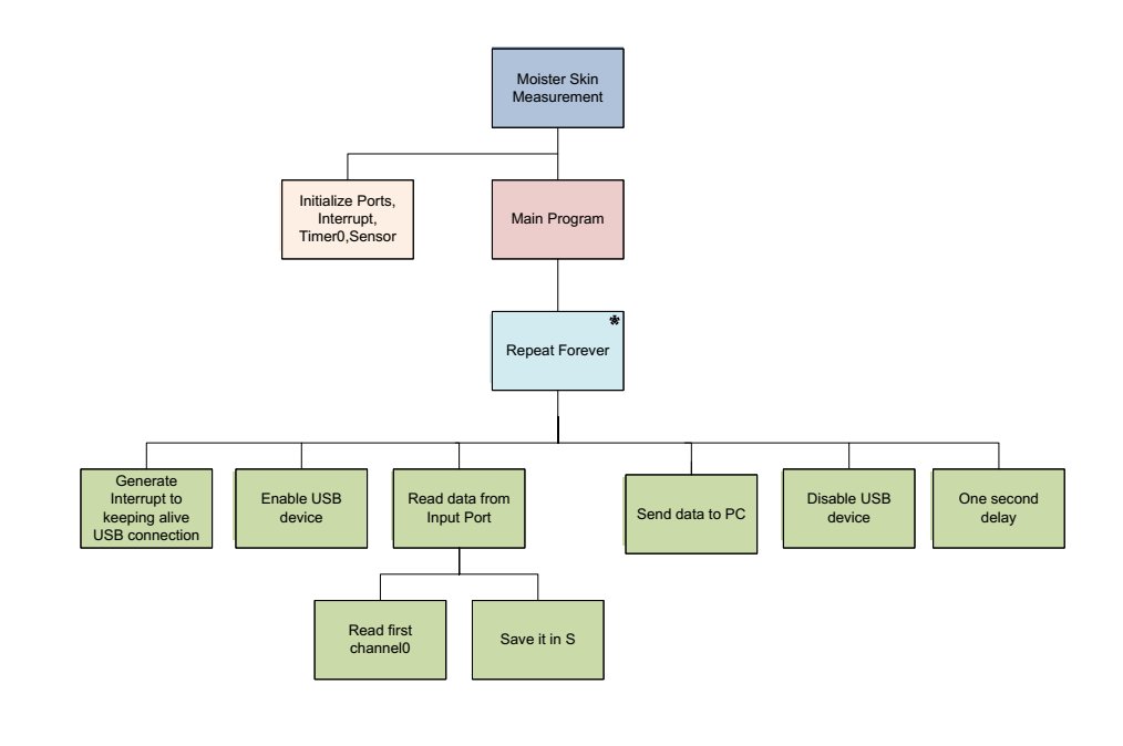
2.1.1-JSD diagram

Diagram explained:

1) The first step in the diagram was initialization of the ports, variables, TIMER0 and interrupts.

2) Next, the main program is executed which is an iteration type of box that indicates an infinite loop (main loop). The loop is important because the microcontroller reboots if the end of the program is reached.

3) Generating interrupt to making the USB link alive during the operation of sending data to the PC. Enabling the interrupt and Timer0 has been described in the previous microcontroller part of this report.

4) The next step on the diagram is to enable the USB device on the chip that carries the data.

5) On the next step the data is read from the specific channel of the input port on the board and the read data was saved in the variable S.

6) In this step the data has been saved on the variable S has to be send to the PC using the USB cable.

7) Disabling the USB device is step to make sure there is no more data can be detected.

8) And finally 1 second software delay is produced in this part the program that makes this loop wait for one second before actually going into next loop.
Following JSD Diagram, the C program Code is written for microcontroller but before writing code it is best to understand the functionalities of the MikroC compiler that is going to be used in this project.
The reason MikroC has been chosen for the project was that as it has the HID library function built in as well as some operation such as the HID terminal can help us to interface the microcontroller with the PC to send and receive data.

2.1.2-MikroC Compiler for PIC:

MikroC is one of the rich feature development tools for the microcontrollers. It is provide the easiest solution without compromising the performance or control for developing embedded systems.

It provides a successful match featuring highly advanced IDE, ANSI compliant compiler, broad sets of hardware libraries, comprehensive documentation and plenty of ready to run examples.

In this part the software has been downloaded and executed by double clicks on MikroC icon on desktop which bring up the window where a new project can be created for this application.

Each application can contains of a single project file (name.ppc) and one or more source file (name.c). The compilation can be done on those file which are part of the project.
First step is to create a project that can be done easily by dropping down the menu and then project>new project which take us in another window that has following parts to fill up:

1. Project name: Each project has to have a name that can be chosen by the user in this project the name selected to be temperature.

2. Project path: this can be any location in c directory or anywhere else where the user wants it to save the file. In this project is selected as default that takes us to the Mkiroelectronika examples folder. C:\ProgramFiles\Mikroelektronika\mikroC\Examples\EasyPic4\extra_exampl es\HID-library\

3. Device: In this part the PIC to be used has to be selected. In this project PIC18F45550 was selected as it is going to be use on board.

4. Clock: This gives more capability to the user to select clocking user want to use on their project. In this project 48MHz was selected. The rest of device flag has to be selected by default. By clicking on save and then ok the software will create new project and empty source file that can be name by the user later.

In this file the C coding for microcontroller is written that operates as it has been explain by JSD Diagram method previously.
In this part before writing the code software for this project a brief description of some of the library functions such as the USB HID and the ADC used in this application is as follows:

i. ADC library function:

This library function can be used to read 10-bit unsigned data value from the specific channel. This value is saved into unsigned long variable for more operation. The prototype for this function is: Unsigned Adc_Read (char channel);

ii. USB HID library function:

MikroC has a library that enables the user to connect and work with the Human Interface Device (HID) via Universal Serial Bus (USB). The HID is a type of computer device that enable the user to interact and take input directly from other input humans (microcontroller input).
In the case of using the PIC18F4550 microcontroller or any other PIC that has USB device built in the following USB library function can be used:
HID_Enable: This function has been used to enable the USB communication that has to be called before any other function of this library and it does not return any data. The function has two arguments which have to be set before using them (read buffer address, write buffer address).

HID_Read: This function is used to get data from the USB bus and store received data into the read buffer. This function does not have any argument but it does

return the number of characters that has been stored in the receive buffer previously.

HID_Write: This function use to send data from the write buffer to the USB bus. The function does not return any data. To use this function has to be careful to copy the same buffer name that has been specified in the initialization and length of data that is going to be send has to be specified in the function argument.

HID_Disable: This function always use at the end of this library function and disable the USB communication. This function does not have any argument and returns no data. Any project that uses the USB library should include a descriptor source file that contains of a vendor ID and name, a product ID and name, a report length (input/output) and other relevant information. In MikroC this can be created directly by using the USB HID terminal tools.

Bring down the menu and then tool>HID terminal after clicking on the HID terminal, it will be open. On this window click on the descriptor that will go to next window. In this window fill up all the descriptor information as shown in Figure (17) and click on create button.

USB HID library function

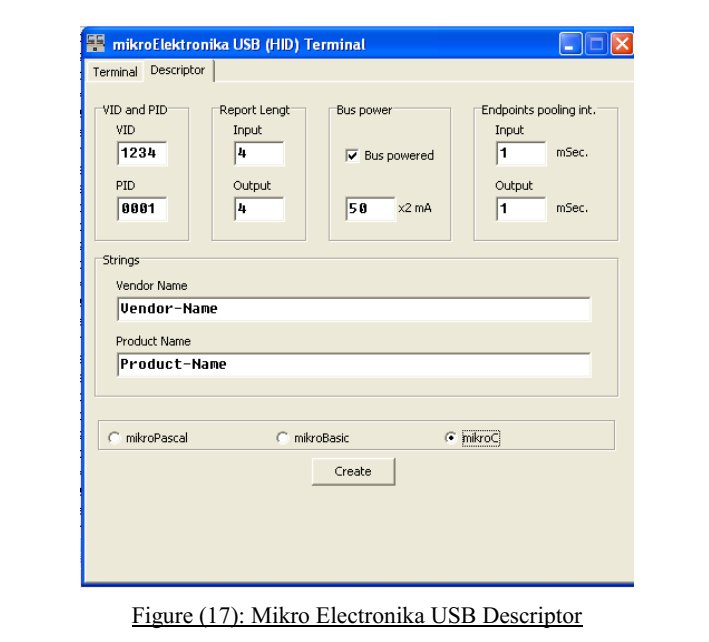
The vendor ID has been set to 1234 (equvalient to decimel 6460) and the Product ID to 1 which was provided by the USB-IF (www.usb.org) which is non-profit corporation that provides software and hardware to help developing and testing products.

By clicking on create button and selecting the project location the compiler will create the USBdsc.c descripter file that shown in appendix.

This file has to be added to the project with either using mikroC IDE tools or include to the project by using #include on the program file.
The program has to have the function to keeping alive the USB connection by sending message to the PC every few millisecond.

This can be achieved by setting up a interrupt that uses the Timer0 to over flow every 0.832ms and inside interrupt service routine the USB function HID_InterruptProc has to be called following that the Timer (TMR0L) is reloaded and the timer interrupts are reenabled just before returning from the interrupt service routine.

2.1.3-Microcontroller clock:

The PIC18F4550 microcontroller requires a 48MHz clock frequency for its USB module and the clock range of 0 to 48MHz is needed for the microcontroller‟s CPU. In this project the CPU clock has been set to 48MHz. this setting has been done using MikroC compiler.
The circuit is shown in Figure (18) illustrate the PIC18F4550 clock circuit. As it is shown in the circuit it consist of following components that has to be set in order to clock in the specific clock frequency:

A 1:1 – 1: 12 PLL prescaler and multiplexer

A 4:96MHz PLL

A 1:2 – 1:6 PLL postscaler

A 1:1 – 1:4 oscillators postscaler

2.1.3-Microcontroller clock

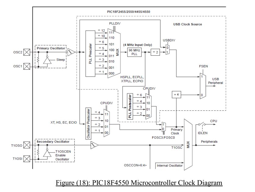
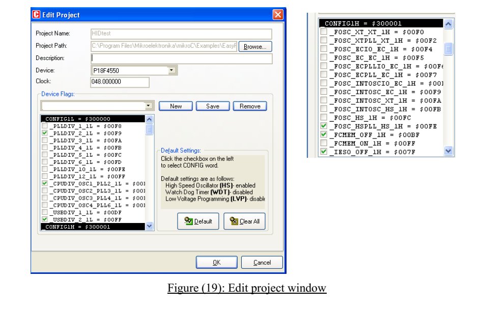
As it has been mentioned before the crystal frequency is 8MHz. In order to set the microcontroller and the USB module operate with 48MHz clock, the following has to be selected in the Edit Project option of MikroC IDE:

The _PLL_DIV2_1L was selected that makes 8MHz clock is divided by 2 to produce 4MHz at the output of the PLL prescaler multiplexer. The output of the 4:96MHz PLL is 96MHz now. It needs further to be divided by 2 to give 48MHz at the input of multiplexer USBDIV.

The _USBDIV_2_1L has been selected to provide a 48MHz clock to USB module and 2 for the PLL postscaler.

The CPUDIV_OSC1_PLL2_1L has been selected to choose PLL as the clock source.

The _FOSC_HSPLL_HS_1H has been selected to choose a 48MHz clock for the CPU.

The CPU clock has been set to 48MHz using the Edit Project option of MikroC IDE.

Figure (19) shows the setting that has been done in the MikroC Edit Project option in order to select 48MHz clock frequency for the USB operation and the CPU clock.

MikroC Edit Project option in order to select 48MHz clock frequency

The source code main program file for the microcontroller that shown in appendix 1 has been written base on the JSD Diagram and the information was provided in previous part of the report. More details of source code will be given in the following part of report.

2.1.4-Main Program for Microcontroller:

This program has been written to connect the PIC18F4550 microcontroller to the PC using a USB cable. One of main important aspect that should be taken into consideration when the USB link is going to be use in any embedded design is to make sure that the USB link is alive during any operation of the bus. The microcontroller is supposed to obtain the data from a temperature sensor that has been connected to the channel0 of the microcontroller. The data was obtained from the sensor is in Celsius and has to be sent to the PC every one second to get display on the screen.

The Visual Basic is used to display the sensor value on the screen that will be explained later in this report. The PIC18F4550 is operates from the 8MHz crystal however the CPU clock frequency and the USB module had set to 48MHz.

The temperature data sent to the PC as 4 digit integer number and it has to be in Celsius.
The main program has been broken down into following sections that make it easier to explain and understand.
1. Include USB Descriptor: The first and important part of this project is to include the USBdsc.c file to the main program which enables the program to use the USB library for the function that will be use later in main program file. This can be done in two ways either using MikroC IDE tool that enable user to add file to the project or simply added to main program using #include option follow by location of file.
2. Define Variable: The second part of each coding will be variable definition that is going to be used in coding. As it shows in code there are a number of unsigned

variables has been used to carry the sensor data and three arrays. One to store first read data from the sensor and another two to be used for write and read buffer, to get easily spot the write buffer name has been changed to the temperature that is going to be used to carry data to the PC.
3. Initialization function: In this part of the code, the PORTA was set as an input by assigning the TRISA to 0xFF and the PORTB as an output by assigning the TRISB to 0x00. The input was set as an analog and +5 reference by setting ADCON1 = 0x00 and analog to digital clock was set to Fosc/64, 8TAD by setting ADCON2 = 0xA6. The way to do this setting was described with the registers well in the PIC18F4550 part of this report.
4. Interrupt function: The interrupt function was used in this program to keep alive the USB link during communication or sending data. The function is keeping link alive by sending a message every 0.832ms and is placed on interrupt service routine (HID_InterruptProc). Timer0 is loaded with 100 that produce 0.832ms overflow time delay and enabling and disabling the interrupt all was described previously on the PIC18F4550 part of the report. 5. Removing blank function: This function is designed to remove extra blanks and digits, as only 4 digits of input data have to be screened out on the PC‟s screen.
6. Main loop: The initialization function (System_init) is the first function to be called in the main loop after initialization the interrupt function that contains of three functions is activated as following the first function (Interrupt_Dis) disabled all the interrupts, the second function (Timer0_init) activated timer0 as well as loading it with 100 to make 0.832ms delay and the third and last function (Interrupt_En) is to enable the interrupt. All setting part of these function has been describe in details previously in the PIC18F4550 part of this report.

The next function that has to be activated in the main loop is the HID USB. The HID enable function was described previously in the report used to enable the Human Interface Device before any other the USB functions. The function, as described before has two arguments write buffer (&Temperature) and read buffer (&Read_buffer). The write buffer was used to store and send input data to the host computer.
The next process was infinite loop which was added to the main loop as the microcontroller never stops the main program has to be in infinite loop.

The first operation is the infinite loop is to read the input voltage data from channel0 (AN0). In this design the input channel is connected to the potentiometer on the board. The input data from potentiometer will be stored in the “Vin” variable, was defined before in the initialization. The store data will be converted to voltage and get stored in the Voltage variable by following equation: Voltage = Vin x 5/1024 Next step is to convert this input voltage to temperature in Celsius that can be done by following equation: Celsius = (Voltage × 100) As the data needs to screen out as a 4 digit integer, the Celsius data was converted to integer and the result was stored on the Cint variable. The following equation was used to do that: Cint = (int) Celsius
To be able to test the software and checking the output data the PORTB was define in this part which enabled the user to output data on the PORTB LEDs for testing purposes. As the USB function can only send data in string, the integer input data was converted to string and was stored in the op array that defined in the beginning of the coding program. The op array can take up to 12 data sizes. As 4 digits has to screen out the remove blank function will be use in this line to take 4 first data from the op array and remove

leading blank of the array. The modify op array was stored it in the temperature buffer array (write buffer) to be send by the next function. The next function is Hid_Write (&Temperature, 4) which was used to send 4 digits to the PC using the USB bus.
As the program should updated every second to satisfy specification, in this part one second software delay was added to the program. This was done by following line of code.

Delay_ms (1000);

The program is in the infinite loop to get input data from a sensor and send it to the PC via the USB bus every one second.

Finally the Hid_Disable function was used to disable the human interface device at the end of the main loop however the program will be stock in the infinite loop after that. The main program for the microcontroller was shown in appendix 1.
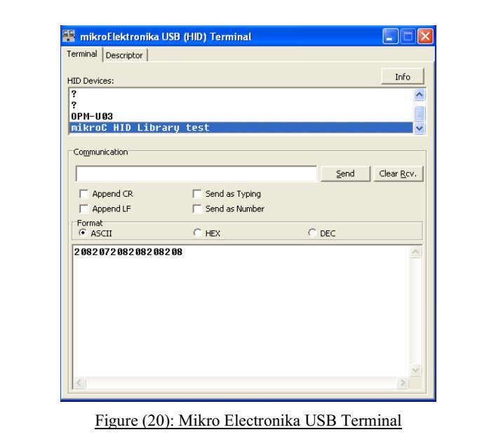
Program testing:

After the program was written, the design code was checked using MikroC IDE software. The software has the HID terminal feature which enables the designer to output the data being send by the microcontroller.
The coding program was loaded into the microcontroller using the PICFlash software by connecting the USB programmer to the board and the PC. The USB cable was connected to the PC and the data was monitored from HID terminal by simply selecting device which was added when the USB cable was connected.

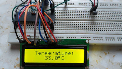
The data was output on the USB terminal every second as was expected. Figure (20) shows the data was output by the HID terminal.

Program testing

2.2-PC Software:

The PC software part of this project is based on Visual Basic. The software program was written to achieve the detection of any USB connectivity operation as well as outputting the input data sent by the microcontroller on the USB bus as 4 bit integers.

The Visual Basic program was used in this project is base on the USB utility which known as Easy HID USB wizard.

The following software programs were used in the project to achieve the aim of screening out the data on the host computer‟s screen.

2.2.1-Easy HID USB wizard

Easy HID USB wizard is a software that can be use to generate an initial template file for the USB PIC and Visual Basic framework.

The software was developed by Mecanique and it can be downloading free of charge from their website (www.mecanique.co.uk).

The software was designed to work with the USB 2.0 and the user does not need to develop any driver to use it as the window XP operating system has the HID based USB driver. The generated code by Easy hid can be expand in such way that fulfils requirement. The following step was taken in order to generate the template code for the Visual Basic:
The first step was to load the zip file and install software by double clicking on set up icon.
After the software was installed, it can be run by double clicking on the icon that appeared on desktop after installation.
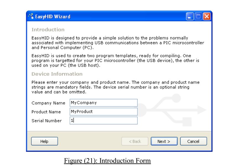
After running the software, the following window will pops up that needs to be filled up by company name, product name and serial number as it shown:

Easy HID USB wizard

By clicking next, the next form will be display that has the Vender ID and Product ID as it shown in following form. The vender IDs are unique and issued by the USB implementer (www.usb.org). Mecanique has its own vender ID and can issue a set of Product IDs for each product with low cost to be use all over the world with the unique vender and product ID. In this project vender and product ID was selected as shown in Figure (22) which is use for testing purposes.

Mecanique has its own vender ID a nd can issue a set of Produc

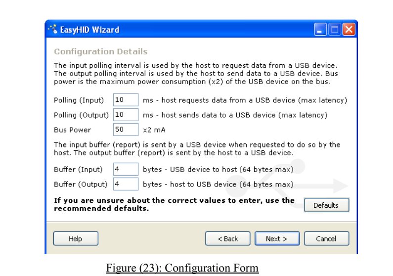
The next form that appear after clicking next, has different parameters such as polling interval for input and output as well as bus maximum power consumption. But the main important parameter in this part that has to be changed according to the project requirement is the input and output buffer size.
These sizes define the number of bits will be send or receive during a USB transaction between the PC and the Microcontroller. In this project both of the input and output was selected to be 4 bits as 4 bits input data are going to be receiving from the microcontroller.

These sizes define the number of bits will be send or receive during a USB

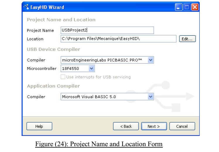
In the next form the project name and location has to be selected as well as compiler and Microcontroller that is was selected to be used by the project. these part and location was selected as shown in Figure (24):

Microcontroller that is was selected to be used by the project

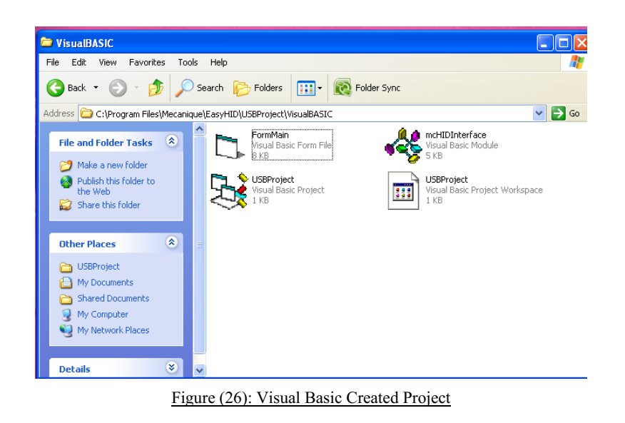
Clicking next will generate the Visual Basic template file in the selected directory which was defined in previous form as shown in Figure (25):

Visual Basic template file in the selected directory

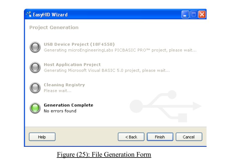
The file was generated by the Easy HID software has consist of a blank form (FormMain.frm), a module file (mcHIDInterface.BAS), and a project file (USBProject.vbp) as shown in Figure (26). The generated project file can be opened by the Visual Basic for more expansion and modification to satisfy the project requirements.

Visual Basic for more expansion and modification to satisfy the project requirements.

2.2.2-Microsoft Visual Basic 6.0:

Visual Basic is a programming language which can be use to develop window based applications and games.

There are numbers of the programming languages available for developing applications but the following benefits makes Visual Basic good software to use in this project:
It is easy to learn and use programming language compare with others (visual C++, etc).

The source availability for learning as it is much more popular compare with others.

There are number of tools (shareware & Freeware) on internet that can help to spare some programming time. Such as the Easy hid wizard who was used to create template file for the USB hid.
The template file was created with Easyhid was opened with Visual Basic by simply download and run Visual Basic6.

By selecting menu and open project (file> project> open project) the directory where project was created in previous part by Easy hid was selected and opened.
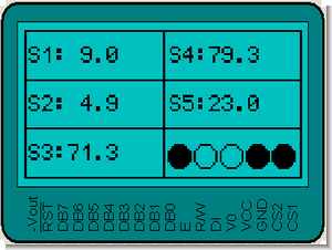
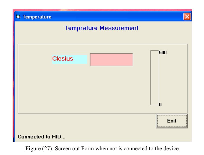
The opened project has two file (Mainform & HIDDLLInterface). The Mainform was modified and expanded in order to screen the input data as shown in the following Form and has the following controls.

Figure (27) illustrate the Form was displayed when the program was not connected to the device.

Microsoft Visual Basic 6.0

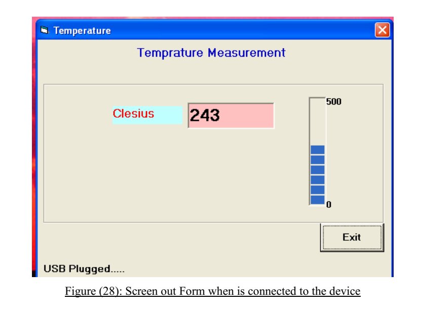
And when the device was connected to the PC using the USB cable the Form was appeared as shown in Figure (28).

connected to the PC using the USB cable

In this part of report more details was given from the expansion part of the Mainform file program in order to display above output Form compare with the blank Form was created by the Easy hid.

a) The first part was added to the template file generated by Easy hid was to display messages on the Form that indicated Form was connected to HID and USB plugged, unplugged. This was obtained by dragged a label to the bottom part of Form where the message displays and was renamed to lblstatus and following message was added to the HID connect function in the Mainform coding part of program to get display as this function being executed by the program, when it is running.

lblstatus = “Connected to HID…” The following messages was added to the USB plugged and unplugged functions in order to display following messages in the case of connection or disconnection of the USB cable as shown here and in the appendix part of report. lblstatus = “USB Plugged…..” lblstatus = “USB Unplugged…..”
Adding these output messages to the end of each operation in the Mainform, will create output message whenever the program executing each specific function.

b) The next and important subroutine has been added the program was the onRead function used to catch data from the USB bus was sent by the microcontroller and display it on the screen.

The subroutine has a global variable (temperature) which stores 4 digits input data and one digit Report ID into 5 buffer inputs is sending from the microcontroller.

The first buffer (BufferIn (0)) always carry Report ID about the packages was sent from the microcontroller. The next 4 buffers (BufferIn (1), BufferIn (2), BufferIn (3), BufferIn (4)) are the actual 4 bits data sent as a string of character to the PC.

These characters were stored in string temperature variable and were displayed by textbox (txtno) in next line of coding program.

Progress bar was another technique was used to output temperature on the bar but as it can output only the integer data the output has to convert from the character to the integer.

All these operations were created and are shown in OnRead subroutine of Mainform appendix.
c) The next step was to add the command button in the bottom part of Form, the following subroutine (key_click) was added in order to stop and exit from the program. Form_Unload (0);
d) The labels such as the temperature measurement, Celsius and number were added to the Form to specify what each control does on the Form. By simply add a label and change its name to the name needed and located it next to the control.
e) At the labels and controls was modified to display as it needed by simply changing fonts, size, etc in their properties control page.

The main coding for the Form is shown in appendix3and interface in appendix 4.

2.2.3-USBTrace USB protocol analyzer

There are number of USB protocol analyzer in the market that can be use to check data transaction on the USB bus. Some are hardware based which make them more expensive and some are software based that make them cheaper compare with hardware based one.
The USBTrace is one of the software based analyzer that was developed by SysNcleus (www.sysnucleus.com), in this report the USBTrace USB protocol analyzer was used to monitored data on the USB bus in the case of project not operating as it was expected because of any problem. A limited time demo version of USBTrace is available on manufacture‟s web site.

The following steps shows in this section illustrate processes was taken place in order to use the software to monitor data was sent by the microcontroller to the PC using the USB bus:

The first step was to download and install program from manufacture‟s website.

The next step was to double click on the USBTrace icon on the desktop which runs the program and the Figure (29) window will appear on the screen.

USBTrace USB protocol analyzer

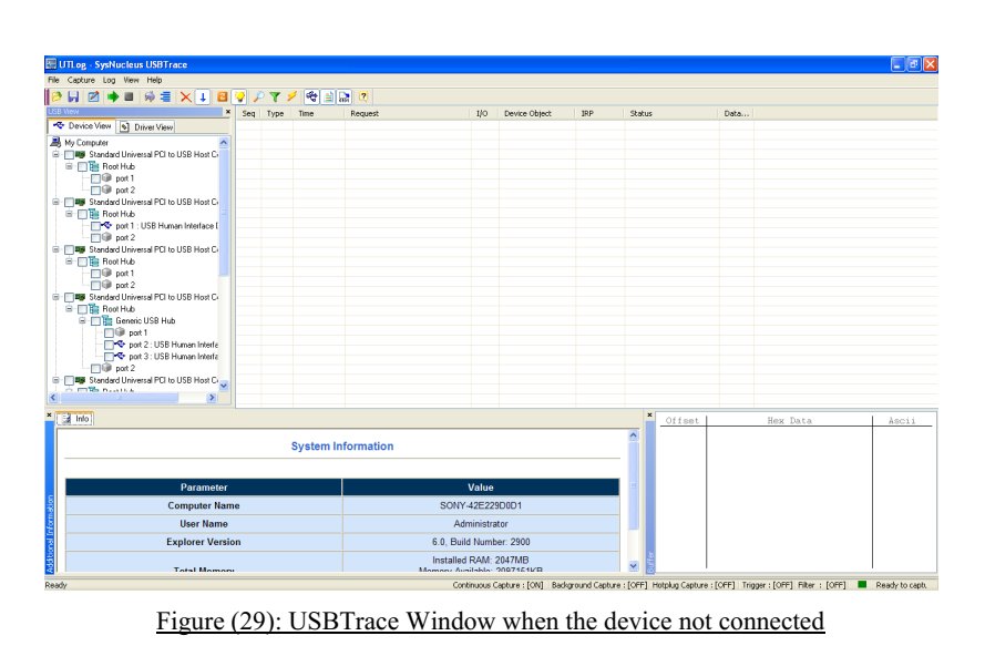
The microcontroller was connected to the USB port of the PC which was detected by the program and a new human interface device was added to the left part of window.

The device was added in the previous step was selected by clicking on the box located next to the HID device.

The data is captured by clicking on the green arrow located on the top left of the menu.

The START OF LOG message was appears in the middle of the screen as the button was clicked and data was captured by the program every second as it was expected.
The captured data was indicated by green color this shown in Figure (30).

The captured data was indicated by green color this shown in Figure (30)

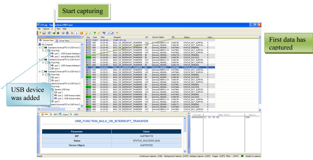
By moving the curser over each packet, the pop up window will appear that gives more information about packet and data has been send in hexadecimal.
By clicking on specific packet, the data value of data in Hexadecimal and ASCII will appear on bottom left of screen as shown in previous figure.
With this software after checking the data on the USB bus and comparing it with the data was expected to screen out on the PC‟s screen.

The designer can work out where the problem starts by observing and comparing the two data streams. The software can be great help to spot the problem in the design by simply monitoring and checking the data on the bus.

5) Results & Discussions:

The project was designed, built and tested. The test results concludes that the software functions as expected from design specification and it is satisfies all requirements. The test of the project was relatively trouble-free part of the project that can be done by going through following steps:

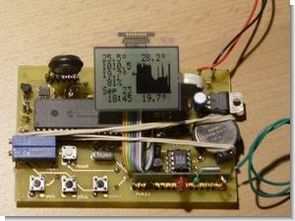
The first step was to construct hardware by placing the PIC18F4550 in the EasyPIC4 development board and activate the part of board is going to be used in the project.
The second step was to load the program into PIC18F4550 microcontroller by connecting board to the PC via the USB 2.0 programmer port and load the program using MikroC compiler and PICFlash2 software.
Next step was to run the visual basic program that detect human interface device and catch data and output it on the screen.
And finally connect the USB connector to the PC that establishes communication and sends data every second. As the microcontroller connects to the PC‟s port for the first time, a message should pops up on the bottom of screen to indicate the human interface device was recognized by the PC.
This can be checked through device manager too. The operation indicates the VIP and PID were set to the right values. Connecting the USB connector makes Visual Basic program to recognize the device and display out USB Plugged message and start to catching and displaying data on the Form.

The project works as it was expected and it satisfies the customer specification Every devices and software has been used in this project had advantages over other similar technology on the market, some described in following:
The microcontroller PIC18F4550 had 10-bit analog to digital conversion as well as the USB 2.0 technology built in one chip.
The EasyPIC4 development board was used as it had all the hardware components needed for the project all on one board built in and was used before for other designed project which made me more familiar to work with its operation compare with other development board.
MikroC compiler was used as it was easy to use and had the HID terminal that could generate the USB descriptor file as well as enabling user to communicate with the microcontroller through the USB bus without any other software.
Visual Basic software was used as the designer has knowledge of how to using software and it is easier to used and understand compare with other version such as Lab view and Visual C++.
Easy HID software was used to generate initial template file for Visual Basic framework which makes design easier.
USBTrace protocol analyzer was used as it is software base, easy to use and cheaper compare with other protocol analyzer in the market.

6) Conclusions & Future works:

The designed system can get input analog signal from a temperature sensor and output measured temperature in Celsius on the screen. The output data is updating every second. Using the USB 2.0 technology to send data from sensor to the host computer was one of the main challenges in this project which was involved with interfacing and protocols.
The following changing can be made to the system that can improve the system to be used by any other purposes that involves with sending data using USB 2.0 technology.

The potentiometer was used in the project to illustrate the analog signal as a temperature sensor. However in the case of where the sensor was defined, this can be change simply by setting the PORTA as an input and connect the sensor to the port. Choosing the PORTA as an input was done by simply disconnecting JP15 in A/D converter part of EasyPIC4 development board.

The system was designed to detect analog signal from the input, but in the case of the digital sensor is going to be used to the input port. The ADCON1 control register has to reconfigure to digital and some part of calculation in the microcontroller coding has to get change.

The input sensor can be increase as some device works with more than one sensor by specifying more input channels to read the data inputs and store them in larger write buffer array size that used to hold data on microcontroller part of program as well as expanding Visual Basic coding in such way that enable program to separate inputs data and output them in deferent textboxes on the form. Another way to do this is to use multiplexer to switch from one channel to another in each moment of time.

The design system can use wireless technology in order to establish communication between the device and the host computer to sending the input data from a sensor to the PC for more operation and store entire data in a database. The data however can be sent using apache software from one place to another for the user attention.

7) Project Planning:

This chart deals with planning and management of the project. Planning and management of any project is basically done following the basic structure as to „„WHERE YOU ARE‟‟ and „„WHERE DO YOU WANT TO GO‟„and finally giving an idea „„HOW TO GET THERE‟„.
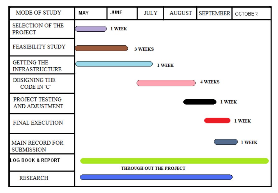
Project Planning

Gantt chart:

The expected duration of the project is 12 Weeks, which is divided as mentioned above.
NOTE: The stipulated timings mentioned to complete the project might change as it is the maximum expected duration, and there is every chance to complete it early.

8) References and Appendices:

8.1. References:

1. USB Mass Storage by Jan Axelson 2. USB Complete by Jan Axelson 3. Advanced PIC Microcontroller Projects in C by Dogan Ibrahi

m 4. EasyPIC4 u

ser manual http://www.mikroe.com/pdf/easypic4/easypic4_manual.pdf 5. PIC18F4550 manual http://ww1.microchip.com/downloads/en/devicedoc/39632e.pdf 6. MikroC user manual http://www.mikroe.com/pdf/mikroc/mikroc_manual.pdf 7. Wikipedia website http://en.wikipedia.org/wiki/Universal_Serial_Bus 8. Visual Basic in easy step by Tim Anderson

8.2. Appendices:

Appendix 1: Main program For Microcontroller:

/*………………………………………………………………..
USB BASED SKIN MOISTURE MEASUREMENT
=============================================
In this project a PIC18F4550
type microcontroller is connected to a PC through the USB
cable.
In addition, a Temperature sensor is connected to analog port AN0 of the microcontroller.
The microcontroller reads the sensor and sends it to the PC every second.
The PC displays the reading
on the screen.
A Visual Basic program runs on the PC which reads the sensor from the USB port and
then displays it on a form.
The microcontroller is operated from
an
8MHz crystal, but the CPU clock frequency is
increased to 48MHz.
Also, the USB module ope
rates with 48MHz.
The Temperature is sent to the PC in Celsius as a 4 digit integer number.
Author: Siamak Sarjoghian
Date: September 2010
File: Temperature.c
==============================================
…………………………………………..
……………………..*/
unsigned char i,j;
unsigned long Vin, Cint;
unsigned char op[12], Temperature[4], Read_buffer[4];
float Voltage,Celsius;
void System_init(void);
void Interrupt_Dis(void);
void Interrupt_En(void);
void Timer0_init(void);
void
Remove_blank(void);
//
——————————————————–
//
// Timer interrupt service routine
//
//
——————————————————–
void interrupt()
{
HID_InterruptProc(); // Keep alive
TMR0L = 100; // Reload
TMR0L
INTCON.TMR0IF = 0; // Re
enable TMR0 interrupts
}
//
——————————————————–
// System_init(void)
// This function initializes the system.
// Pins used:
// Set inputs as analog, Ref=+5V
// Set A/D clock = Fosc/64, 8TAD
// Set PORT A as inputs
// Set PORT B as outputs
//
——————————————————–
void System_init(void)
{
ADCON1 = 0x00;
ADCON2 = 0xA6;
TRISA = 0xFF;
TRISB = 0X00;
}
//
——————————————————–
//
void Interrupt_Dis(void)
//
// Set interrupt registers to power
on defaults
// Disable all interrupts
//
//
——————————————————–
void Interrupt_Dis(void){
INTCON=0x00;
INTCON2=0xF5;
INTCON3=0xC0;
RCON.IPEN=0x00;
PIE1=0x00
;
PIE2=0x00;
PIR1=0x00;
PIR2=0x00;
}
//
——————————————————–
// void Interrupt_En(void)
//
// Set interrupt registers to power
on defaults
// Enable all interrupts
//
//
—————————————————-
—-
void Interrupt_En(void){
INTCON = 0xE0;
}
//
——————————————————–
// void Timer0_init(void)
//
// Configure TIMER 0 for 3.3ms interrupts. Set prescaler to 256
// and load TMR0L to 156 so that the time interval for ti
mer
// interrupts at 48MHz is 256.156.0.083 = 3.3ms
//
// The timer is in 8
bit mode by default
//
//
——————————————————–
void Timer0_init(void){
T0CON = 0x47; // Prescaler = 256
TMR0L = 100; // Timer count is 256
156 =
100
INTCON.TMR0IE = 1; // Enable T0IE
T0CON.TMR0ON = 1; // Turn Timer 0 ON
}
//
——————————————————–
// Remove_blank(void)
// Remove leading blanks from op array.
// The function save first 5 character in temperature arra
y.
//
——————————————————–
void Remove_blank(void){
for(j=0; j<4; j++)Temperature[j]=’ ‘;
j=0;
for(i=0;i<=11;i++)
{
if(op[i] != ‘ ‘) // If a blank
{
Temperature[j]=op[i];
j++;
}
}
}
//
————————————-
——————-
//
// Start of MAIN program
//
//
——————————————————–
void main()
{
System_init();
Interrupt_Dis();
Timer0_init();
Interrupt_En();
//
——————————————————–
// Enable
USB port
//
——————————————————–
Hid_Enable(&Read_buffer, &Temperature);
Delay_ms(1000);// Wait 1 second
//
——————————————————–
//
// Endless loop. Read
Temperature from the A/D converter,
// convert into Celsius
and send to the PC over the
// USB port every second
// forever loop
//
//
——————————————————–
for(;;)
{
Vin = Adc_Read(0); // Read from channel 0 (AN0)
Voltage
= (Vin * 5.0) / 1024.0; // In Voltage = Vin x 5/1024
Celsius = (Voltage * 100.0); // convert voltage to Temperature in Celsius
Cint = (int)Celsius; // As an integer number
PORTB = Cint;
LongToStr(Cint,op); // Convert to string in “op”
Remove_blank();
//To remove blanks
characters
from op and save it in temperature.
//
——————————————————–
// Send Temperature (in array Temperature ) to the PC
//
——————————————————–
Hid_Write(&Temper
ature,4); // Send to USB as 4 characters
Delay_ms(1000); // Wait 1 second
}
//
——————————————————–
// Disable USB port
//
——————————————————–
Hid_Disable();
}


Appendix 2: USB Descriptor File:

//**********************************************************************
********
//
// File Version 1.01
//
//**********************************************************************
********
#include “Definit.h”
#include “VARs.h”
//*****
*****************************************************************
********
// The number of bytes in each report,
// calculated from Report Size and Report Count in the report descriptor
//********************************************************************
**
********
unsigned char const HID_INPUT_REPORT_BYTES = 4;
unsigned char const HID_OUTPUT_REPORT_BYTES = 4;
unsigned char const HID_FEATURE_REPORT_BYTES = 2;
//**********************************************************************
********
// By
te constants
//**********************************************************************
********
unsigned char const NUM_ENDPOINTS = 2;
unsigned char const ConfigDescr_wTotalLength =
USB_CONFIG_DESCRIPTOR_LEN + USB_INTERF_DESCRIPTOR_LEN +
USB
_HID_DESCRIPTOR_LEN + (NUM_ENDPOINTS *
USB_ENDP_DESCRIPTOR_LEN);
unsigned char const HID_ReportDesc_len = 47;
unsigned char const Low_HID_ReportDesc_len = HID_ReportDesc_len;
unsigned char const High_HID_ReportDesc_len = HID_ReportDesc_l
en >> 8;
unsigned char const Low_HID_PACKET_SIZE = HID_PACKET_SIZE;
unsigned char const High_HID_PACKET_SIZE = HID_PACKET_SIZE >> 8;
//**********************************************************************
********
// Descriptor Tables
//**
********************************************************************
********
unsigned char const DescTables[USB_DEVICE_DESCRIPTOR_ALL_LEN*2] = {
// Device Descriptor
USB_DEVICE_DESCRIPTOR_LEN, 0, // bLength
Length of Device
d
escriptor (always 0x12)
USB_DEVICE_DESCRIPTOR_TYPE, 0, // bDescriptorType
1 = DEVICE
descriptor
0x00, 0, // bcdUSB
USB revision 2.00 (low byte)
0x02, 0,
// (high byte)
0x00, 0, // bDeviceClass
Zero means each interface operates
independently (class code in the interface descriptor)
0x00, 0,
// bDeviceSubClass
0x00, 0, // bDeviceProtocol
EP0_PACKET_SIZE, 0, // bMaxPacketSize0
maximum size of a
data packet for a control transfer over EP0
0x34, 0,
// idVendor
Vendor ID (low byte)
0x12, 0, // (high byte)
0x01, 0, // idProduct
Product ID (low byte)
0x
00, 0, // (high byte)
0x01, 0, // bcdDevice
( low byte)
0x00, 0, // (high byte)
0x01, 0, // iManufacturer
String1
0x02, 0, // iProduct
String2
0x00, 0, // iSerialNumber
( None )
0x01, 0,
// bNumConfigurations
1
// Configuration Descriptor
USB_CONFIG_DESCRIPTOR_LEN, 0, // bLength
Length of
Configuration descriptor (always 0x09)
USB_CONFIG_DESCRIPTOR_TYPE, 0, // bDescri
ptorType
2 =
CONFIGURATION descriptor
ConfigDescr_wTotalLength, 0, // wTotalLength
Total length of this
config. descriptor plus the interface and endpoint descriptors that are part of the
configuration.
0x00, 0,
// ( high byte)
0x01, 0, // bNumInterfaces
Number of interfaces
0x01, 0, // bConfigurationValue
Configuration Value
0x00
, 0, // iConfiguration
String Index for this configuration (
None )
0xA0, 0, // bmAttributes
attributes
“Bus powered” and
“Remote wakeup”
50, 0,
// MaxPower
bus
powered draws 50*2 mA from
the bus.
// Interface Descriptor
USB_INTERF_DESCRIPTOR_LEN, 0, // bLength
Length of
Interface descriptor (always 0x09)
USB_INTERFACE_DESCRIPTOR_TYPE,
0, // bDescriptorType
4 =
INTERFACE descriptor
0x00, 0, // bInterfaceNumber
Number of interface, 0 based
array
0x00, 0, // bAlternateSetting
Alternate setting
NUM_ENDPOINTS, 0, // bNumEndPoints
Number of endpoints
used in this interface
0x03, 0, // bInterfaceClass
assigned by the USB
0x00, 0, // bIn
terfaceSubClass
Not A boot device
0x00, 0, // bInterfaceProtocol
none
0x00, 0, // iInterface
Index to string descriptor that
describes this interface ( None )
//
HID Descriptor
USB_HID_DESCRIPTOR_LEN, 0, // bLength
Length of HID
descriptor (always 0x09)
USB_HID_DESCRIPTOR_TYPE, 0, // bDescriptorType
0x21 = HID
descriptor
0x01, 0,
// HID class release number (1.01)
0x01, 0,
0x00, 0, // Localized country code (none)
0x01, 0, // # of HID class descriptor to follow (1)
0x22, 0,
// Report descriptor type (HID)
Low_HID_ReportDesc_len, 0,
High_HID_ReportDesc_len, 0,
// EP1_RX Descriptor
USB_ENDP_DESCRIPTOR_LEN, 0, // bLength
length of descriptor
(always 0x07)
USB_ENDPOINT_DESCRIPTOR
_TYPE, 0, // bDescriptorType
5 =
ENDPOINT descriptor
0x81, 0, // bEndpointAddress
In, EP1
USB_ENDPOINT_TYPE_INTERRUPT, 0, // bmAttributes
Endpoint
Type
Interrupt
Low_HID_
PACKET_SIZE, 0, // wMaxPacketSize
max packet size
low order byte
High_HID_PACKET_SIZE, 0, //
max packet size
high order
byte
1, 0, // bInterval
polling interval (1 ms)
// EP1_TX Descriptor
USB_ENDP_DESCRIPTOR_LEN, 0, // bLength
length of descriptor
(always 0x07)
USB_ENDPOINT_DESCRIPTOR_TYPE, 0, // bDescriptorType
5 =
ENDPOINT descripto
r
0x01, 0, // bEndpointAddress
Out, EP1
USB_ENDPOINT_TYPE_INTERRUPT, 0, // bmAttributes
Endpoint
Type
Interrupt
Low_HID_PACKET_SIZE, 0, // wMaxPacketSize
max pa
cket size
low order byte
High_HID_PACKET_SIZE, 0, //
max packet size
high order
byte
1, 0, // bInterval
polling interval (1 ms)
// HID_Report Descriptor
0x06, 0, // USAGE_PAGE (Vendor Defined)
0xA0, 0,
0xFF, 0,
0x09, 0, // USAGE ID (Vendor Usage 1)
0x01, 0,
0xA1, 0, // COLLECTION (Application)
0x01, 0,
// The Input report
0x09, 0, // USAGE ID
Vendor defined
0x03, 0,
0x15, 0, // LOGICAL_MINIMUM (0)
0x00, 0,
0x26, 0, // LOGICA
L_MAXIMUM (255)
0x00, 0,
0xFF, 0,
0x75, 0, // REPORT_SIZE (8)
0x08, 0,
0x95, 0, // REPORT_COUNT (2)
HID_INPUT_REPORT_BYTEs, 0,
0x81, 0,
// INPUT (Data,Var,Abs)
0x02, 0,
// The Output report
0x09, 0, // USAGE ID
Vendor defined
0x04, 0,
0x15, 0, // LOGICAL_MINIMUM (0)
0x00, 0,
0x26, 0,
// LOGICAL_MAXIMUM (255)
0x00, 0,
0xFF, 0,
0x75, 0, // REPORT_SIZE (8)
0x08, 0,
0x95, 0, // REPORT_COUNT (2)
HID_OUTPUT_REPORT_BYTES, 0,
0
x91, 0, // OUTPUT (Data,Var,Abs)
0x02, 0,
// The Feature report
0x09, 0, // USAGE ID
Vendor defined
0x05, 0,
0x15, 0, // LOGICAL_MINIMUM (0)
0x00, 0,
0x26, 0, // LOGICAL_MAXIMUM (255)
0x00, 0,
0xFF, 0,
0x75, 0, // REPORT_SIZE (8)
0x08, 0,
0x95, 0, // REPORT_COUNT (2)
HID_FEATURE_REPORT_BYTES, 0,
0xB1, 0, // FEATURE (Data,Var,Abs)
0x02, 0,
// End Collection
0xC0, 0 // END_COLLECTION
};
//*****************************************************
*****************
********
unsigned char const LangIDDescr[8] = {
0x04, 0,
USB_STRING_DESCRIPTOR_TYPE, 0,
0x09, 0, // LangID (0x0409)
Low
0x04, 0 //
High
};
/
/**********************************************************************
********
unsigned char const ManufacturerDescr[68] = {
34, 0,
USB_STRING_DESCRIPTOR_TYPE, 0,
‘m’, 0, 0, 0,
‘i’, 0, 0, 0,
‘k’, 0, 0, 0,
‘r’, 0, 0, 0,
‘o’, 0,
0, 0,
‘E’, 0, 0, 0,
‘l’, 0, 0, 0,
‘e’, 0, 0, 0,
‘k’, 0, 0, 0,
‘t’, 0, 0, 0,
‘r’, 0, 0, 0,
‘o’, 0, 0, 0,
‘n’, 0, 0, 0,
‘i’, 0, 0, 0,
‘k’, 0, 0, 0,
‘a’, 0, 0, 0
};
//************************************************
**********************
********
unsigned char const ProductDescr[96] = {
48, 0,
USB_STRING_DESCRIPTOR_TYPE, 0,
‘m’, 0, 0, 0,
‘i’, 0, 0, 0,
‘k’, 0, 0, 0,
‘r’, 0, 0, 0,
‘o’, 0, 0, 0,
‘C’, 0, 0, 0,
‘ ‘, 0, 0, 0,
‘H’, 0,
0, 0,
‘I’, 0, 0, 0,
‘D’, 0, 0, 0,
‘ ‘, 0, 0, 0,
‘L’, 0, 0, 0,
‘i’, 0, 0, 0,
‘b’, 0, 0, 0,
‘r’, 0, 0, 0,
‘a’, 0, 0, 0,
‘r’, 0, 0, 0,
‘y’, 0, 0, 0,
‘ ‘, 0, 0, 0,
‘t’, 0, 0, 0,
‘e’, 0, 0, 0,
‘s’, 0, 0, 0
,
‘t’, 0, 0, 0
};
//**********************************************************************
********
unsigned char const StrUnknownDescr[4] = {
2, 0,
USB_STRING_DESCRIPTOR_TYPE, 0
};
//*************************************************************
*********
********
//**********************************************************************
********
// Initialization Function
//**********************************************************************
********
void InitUSBdsc()
{
Byte_tmp_0[0] = NUM_EN
DPOINTS;
Byte_tmp_0[0] = ConfigDescr_wTotalLength;
Byte_tmp_0[0] = HID_ReportDesc_len;
Byte_tmp_0[0] = Low_HID_ReportDesc_len;
Byte_tmp_0[0] = High_HID_ReportDesc_len;
Byte_tmp_0[0] = Low_HID_PACKET_SIZE;
Byte_tmp_0[0] = High_HID_PACKET_SIZE;
DescTables;
LangIDDescr;
ManufacturerDescr;
ProductDescr;
StrUnknownDescr;
}
//**********************************************************************
********


Appendix 3: Visual Basic Main Form Code:

Private Const VendorID = 4660
Private Const
ProductID = 1
‘ read and write buffers
Private Const BufferInSize = 8
Private Const BufferOutSize = 8
Dim BufferIn(0 To BufferInSize) As Byte
Dim BufferOut(0 To BufferOutSize) As Byte
‘ ****************************************************************
‘ w
hen the form loads, connect to the HID controller
pass
‘ the form window handle so that you can receive notification
‘ events…
‘*****************************************************************
Private Sub Form_Load()
ConnectToHID (Me.hwnd)
lblst
atus = “Connected to HID…”
End Sub
‘*****************************************************************
‘ disconnect from the HID controller…
‘*****************************************************************
Private Sub Form_Unload(Cancel As Integer)
DisconnectFromHID
End Sub
‘*****************************************************************
‘ A HID device has been plugged in…
‘*****************************************************************
Public Sub OnPlugged(ByVal pH
andle As Long)
If hidGe
tVendorID(pHandle) = VendorID And hidGetProductID(pHandle) =
ProductID Then
lblstatus = “USB Plugged…..”
End If
End Sub
‘*****************************************************************
‘ A HID device has been unplugged…
‘*********************
********************************************
Public Sub OnUnplugged(ByVal pHandle As Long)
If hidGetVendorID(pHandle) = VendorID And hidGetProductID(pHandle) =
ProductID Then
lblstatus = “USB Unplugged….”
End If
End Sub
‘***********************
******************************************
‘ controller changed notification
called
‘ after ALL HID devices are plugged or unplugged
‘*****************************************************************
Public Sub OnChanged()
Dim DeviceHandle As Long
DeviceHandle = hidGetHandle(VendorID, ProductID)
hidSetReadNotify DeviceHandle, True
End Sub
‘*****************************************************************
‘ on read event…
‘*****************************************************************
P
ublic Sub OnRead(ByVal pHandle As Long)
Dim Temperature As String
If hidRead(pHandle, BufferIn(0)) Then
Temperature = Chr(BufferIn(1)) & Chr(BufferIn(2)) & Chr(BufferIn(3)) &
Chr(BufferIn(4))
txtno = Temperature
‘ Display.Text = txtno
End If
End Sub
‘*
****************************************************************
‘ button key to end program
‘*****************************************************************
Private Sub Key_Click()
Form_Unload (0)
End
End Sub


Appendix 4: HID Interface API Declaration File:

‘ this is the interface to the HID controller DLL
you should not
‘ normally need to change anything in this file.
‘ WinProc() calls your main form ‘event’ procedures
these are currently
‘ set to..
‘ MainForm.OnPlugged(ByVal pHandle
as long)
‘ MainForm.OnUnplugged(ByVal pHandle as long)
‘ MainForm.OnChanged()
‘ MainForm.OnRead(ByVal pHandle as long)
Option Explicit
‘ HID interface API declarations…
Declare Function hidConnect Lib “mcHID.dll” Alias “Connect” (ByVal pHostWin As
Long
) As Boolean
Declare Function hidDisconnect Lib “mcHID.dll” Alias “Disconnect” () As Boolean
Declare Function hidGetItem Lib “mcHID.dll” Alias “GetItem” (ByVal pIndex As Long)
As Long
Declare Function hidGetItemCount Lib “mcHID.dll” Alias “GetItemCount” ()
As Long
Declare Function hidRead Lib “mcHID.dll” Alias “Read” (ByVal pHandle As Long,
ByRef pData As Byte) As Boolean
Declare Function hidWrite Lib “mcHID.dll” Alias “Write” (ByVal pHandle As Long,
ByRef pData As Byte) As Boolean
Declare Function hidReadE
x Lib “mcHID.dll” Alias “ReadEx” (ByVal pVendorID As
Long, ByVal pProductID As Long, ByRef pData As Byte) As Boolean
Declare Function hidWriteEx Lib “mcHID.dll” Alias “WriteEx” (ByVal pVendorID As
Long, ByVal pProductID As Long, ByRef pData As Byte) As Boo
lean
Declare Function hidGetHandle Lib “mcHID.dll” Alias “GetHandle” (ByVal pVendoID
As Long, ByVal pProductID As Long) As Long
Declare Function hidGetVendorID Lib “mcHID.dll” Alias “GetVendorID” (ByVal
pHandle As Long) As Long
Declare Function hidGetProdu
ctID Lib “mcHID.dll” Alias “GetProductID” (ByVal
pHandle As Long) As Long
Declare Function hidGetVersion Lib “mcHID.dll” Alias “GetVersion” (ByVal pHandle
As Long) As Long
Declare Function hidGetVendorName Lib “mcHID.dll” Alias “GetVendorName” (ByVal
pHand
le As Long, ByVal pText As String, ByVal pLen As Long) As Long
Declare Function hidGetProductName Lib “mcHID.dll” Alias “GetProductName” (ByVal
pHandle As Long, ByVal pText As String, ByVal pLen As Long) As Long
Declare Function hidGetSerialNumber Lib “mcH
ID.dll” Alias “GetSerialNumber”
(ByVal pHandle As Long, ByVal pText As String, ByVal pLen As Long) As Long
Declare Function hidGetInputReportLength Lib “mcHID.dll” Alias
“GetInputReportLength” (ByVal pHandle As Long) As Long
Declare Function hidGetOutputRe
portLength Lib “mcHID.dll” Alias
“GetOutputReportLength” (ByVal pHandle As Long) As Long
Declare Sub hidSetReadNotify Lib “mcHID.dll” Alias “SetReadNotify” (ByVal pHandle
As Long, ByVal pValue As Boolean)
Declare Function hidIsReadNotifyEnabled Lib “mcHID.
dll” Alias
“IsReadNotifyEnabled” (ByVal pHandle As Long) As Boolean
Declare Function hidIsAvailable Lib “mcHID.dll” Alias “IsAvailable” (ByVal
pVendorID As Long, ByVal pProductID As Long) As Boolean
‘ windows API declarations
used to set up messaging…
Private Declare Function CallWindowProc Lib “user32” Alias “CallWindowProcA”
(ByVal lpPrevWndFunc As Long, ByVal hwnd As Long, ByVal Msg As Long, ByVal
wParam As Long, ByVal lParam As Long) As Long
Private Declare Function SetWindowLong Lib “user32” Alias
“SetWindowLongA”
(ByVal hwnd As Long, ByVal nIndex As Long, ByVal dwNewLong As Long) As Long
‘ windows API Constants
Private Const WM_APP = 32768
Private Const GWL_WNDPROC =
4
‘ HID message constants
Private Const WM_HID_EVENT = WM_APP + 200
Private Co
nst NOTIFY_PLUGGED = 1
Private Const NOTIFY_UNPLUGGED = 2
Private Const NOTIFY_CHANGED = 3
Private Const NOTIFY_READ = 4
‘ local variables
Private FPrevWinProc As Long ‘ Handle to previous window procedure
Private FWinHandle As Long ‘ Handle to me
ssage window
‘ Set up a windows hook to receive notification
‘ messages from the HID controller DLL
then connect
‘ to the controller
Public Function ConnectToHID(ByVal pHostWin As Long) As Boolean
FWinHandle = pHostWin
ConnectToHID = hidConnect(FW
inHandle)
FPrevWinProc = SetWindowLong(FWinHandle, GWL_WNDPROC, AddressOf
WinProc)
End Function
‘ Unhook from the HID controller and disconnect…
Public Function DisconnectFromHID() As Boolean
DisconnectFromHID = hidDisconnect
SetWindowLong FWin
Handle, GWL_WNDPROC, FPrevWinProc
End Function
‘ This is the procedure that intercepts the HID controller messages…
Private Function WinProc(ByVal pHWnd As Long, ByVal pMsg As Long, ByVal
wParam As Long, ByVal lParam As Long) As Long
If pMsg = WM_HID
_EVENT Then
Select Case wParam
‘ HID device has been plugged message…
Case Is = NOTIFY_PLUGGED
MainForm.OnPlugged (lParam)
‘ HID device has been unplugged
Case Is = NOTIFY_UNPLUGGED
M
ainForm.OnUnplugged (lParam)
‘ controller has changed…
Case Is = NOTIFY_CHANGED
MainForm.OnChanged
‘ read event…
Case Is = NOTIFY_READ
MainForm.OnRead (lParam)
End Select
En
d If
‘ next…
WinProc = CallWindowProc(FPrevWinProc, pHWnd, pMsg, wParam, lParam)
End Function


The post SKIN TEMPERATURE MEASUREMENT appeared first on PIC Microcontroller.


Display temperature on Graphic Liquid Crystal Display using PIC16F877A Microcontroller

$
0
0

Hello everybody welcome back . Today I’m gonna tell how you can display temperature with bar graph on Graphic LCD using PIC microcontroller . The project is very simple to understand if you have concept of

Graphic LCD .The program in this project is written in C and Assembly level language &  the compiler used to write the C code is mikroC PRO for PIC V. 7.1.0 .You can download complete project (C and Asm file with proteus8 file ) from this link temperature on GLCd . 

Graphical Liquid Crystal (GLCD)

Graphical lcds are different from the ordinary alphanumeric  lcds, like 16×1 16×2 16×4 20×1 20×2 etc. They (ordinary) can print only characters or custom made characters. They have a fixed size for displaying a character normally 5×7 or 5×8 matrix. Where as in graphical lcd we have 128×64=8192 dots each dot can be lit up as our wish or we can make pixels with 8 dots ie. 8192/8=1024 pixels. We can design a character in a size which we need. More over we can make a picture on a graphical LCD as well. you can learn more about this LCD on this link Graphic LCD

LM35 Temperature Sensor

The LM35 temperature sensor is a semiconductor sensor. It is available in integrated circuit (IC) form. It has 3 pins and the IC is as shown below.

Display temperature on Graphic Liquid Crystal Display using PIC16F877A microcontroller explained1

Working Principle of temperature sensor :

VT = kT/q

Features of LM35:

  • Calibrated directly in Celsius scale ( Centigrade)
  • Linear +10 mV/0C scale factor
  • 50C Ensured Accuracy (at 250C)
  • Works for -550C to 1500C
  • Operates in the range of 4V to 30V
  • Less than 60µA design drain current
  • Low impedance output, 0.1Ω for 1-mA load
  • Low self heating, 0.80C in still air

Display temperature on Graphic Liquid Crystal Display using PIC16F877A Microcontroller (Code)


// Glcd module connections
char GLCD_DataPort at PORTD;
sbit GLCD_CS1 at RC0_bit;
sbit GLCD_CS2 at RC1_bit;
sbit GLCD_RS at RB3_bit;
sbit GLCD_RW at RB4_bit;
sbit GLCD_EN at RB5_bit;
sbit GLCD_RST at RE2_bit;
sbit GLCD_CS1_Direction at TRISC0_bit;
sbit GLCD_CS2_Direction at TRISC1_bit;
sbit GLCD_RS_Direction at TRISB3_bit;
sbit GLCD_RW_Direction at TRISB4_bit;
sbit GLCD_EN_Direction at TRISB5_bit;
sbit GLCD_RST_Direction at TRISE2_bit;
// End Glcd module connections
char txt[4];
unsigned tmp;
void main() {
Glcd_Init();
Glcd_Fill(0);
ADC_Init();
while(1){
tmp = ADC_Read(0);
tmp = tmp/2.05;
ByteToStr(tmp, txt);
Glcd_Write_Text("o", 60,0, 1);
Glcd_Write_Text(txt, 35,1, 1);
Glcd_Write_Text("TEMP =", 0,1, 1);
Glcd_Write_Text("C ", 70,1, 1);
if (tmp>20) {Glcd_Box(10, 50, 20, 70, 1); }
if (tmp<20) {Glcd_Box(10,50, 20, 70, 0); } if (tmp>40) {Glcd_Box(20, 45, 30, 70, 1); }
if (tmp<40) {Glcd_Box(20, 45, 30, 70, 0); } if (tmp>60) {Glcd_Box(30, 40, 40, 70, 1); }
if (tmp<60) {Glcd_Box(30, 40, 40, 70, 0); } if (tmp>80) {Glcd_Box(40, 35, 50, 70, 1); }
if (tmp<80) {Glcd_Box(40, 35, 50, 70, 0); } if (tmp>100) {Glcd_Box(50, 30, 60, 70, 1); }
if (tmp<100) {Glcd_Box(50, 30, 60, 70, 0); } if (tmp>115) {Glcd_Box(60, 25, 70, 70, 1); }
if (tmp<115) {Glcd_Box(60, 25, 70, 70, 0); } if (tmp>130) {Glcd_Box(70, 20, 80, 70, 1); }
if (tmp<130) {Glcd_Box(70, 20, 80, 70, 0); } if (tmp>140) {Glcd_Box(80, 15, 90, 70, 1); }
if (tmp<140) {Glcd_Box(80, 15, 90, 70, 0); } if (tmp>145) {Glcd_Box(90, 10, 100, 70, 1); }
if (tmp<145) {Glcd_Box(90, 10, 100, 70, 0); }
}
}

Display temperature on Graphic Liquid Crystal Display using PIC16F877A Microcontroller (Schematic Diagram)

Display temperature on Graphic Liquid Crystal Display using PIC16F877A microcontroller explained

PROTEUS SCHAMATIC DIAGRAM WITH ANIMATION

Short Description

The code is very easy to understand . First we have defined Control and DATA pins of graphical LCD to PIC microcontroller . Then after we have displayed some text using function Glcd_Write_Text(“”, ,,); .Since we cannot write box using Glcd_Write_Text(); function we have to make our own box using the function Glcd_Box(x,y,-x,-y,on/off). These box are made to respective temperature and the box is used to represent the temperature . Thats all concept behind this project .
If you have any question about this project please comment below , if you like this project please share this .

The post Display temperature on Graphic Liquid Crystal Display using PIC16F877A Microcontroller appeared first on PIC Microcontroller.

Double sensor interface Indoor/OutdoorThermometer using PIC16F877A Microcontroller

$
0
0

This is a simple project showing you how to read LM35 analog temperature sensor using a PIC microcontroller and LCD 4×20 in Proteus ISIS. In this tutorial we will make a practical use of the ADC. We will use them to show current temperature using two LM35 temperature sensors.

The temperature sensors are connected to the ADC ports of the microcontroller, which takes in the analog signal and gives out digital values across specified ports.

Across the defined output port of the microcontroller, LCD 4×20 is connected with takes the values of the temperature sensors (Indoor / Outdoor) and displays them.
Double sensor interface Indoor/OutdoorThermometer using PIC16F877A Microcontroller

LM35 is a Three-Pins (Vcc,Output,GND) high precision temperature sensor having a resolution of 10mV/C starting at 0V (i.e. an output of 0V represents a temperature of 0C).

So :

10mV —> 1C
20mV —> 2C
500mV —> 50C and so on

Double sensor interface Indoor-OutdoorThermometer using PIC16F877A Microcontroller3

lm35 T-V diagram


ADC is an electronic circuit that converts continuous signals to discrete digital numbers. PIC16F877A  microcontroller built in ADC (analog to digital converter) is used to measure analog voltage. The analog to digital conversion is done by the PIC ADC module. In the code, I’ve used the mikro C library function for ADC.
ADC Library provides you a comfortable work with the module.

Library Routines

  • ADC_Init
  • ADC_Get_Sample
  • ADC_Read

ADC_Init

Prototype voidADC_Init();
Returns Nothing.
Description This routine initializes PIC’s internal ADC module to work with RC clock. Clock determines the time period necessary for performing AD conversion (min 12TAD).
Requires
  • MCU with built-in ADC module.
Example ADC_Init();  // Initialize ADC module with default settings

ADC_Get_Sample

Prototype unsigned ADC_Get_Sample(unsigned short channel);
Returns 10 or 12-bit unsigned value read from the specified channel (MCU dependent).
Description The function acquires analog value from the specified channel.
Parameter channel represents the channel from which the analog value is to be acquired. Refer to the appropriate datasheet for channel-to-pin mapping.  Note : This function doesn’t work with the external voltage reference source, only with the internal voltage reference.
Requires
  • The MCU with built-in ADC module.
  • Prior to using this routine, ADC module needs to be initialized.
  • Before using the function, be sure to configure the appropriate TRISx bits to designate pins as inputs.
Example unsigned adc_value;…

adc_value = ADC_Get_Sample(2);    // read analog value from ADC module channel 2

ADC_Read

Prototype unsigned ADC_Read(unsigned short channel);
Returns 10 or 12-bit unsigned value read from the specified channel (MCU dependent).
Description Initializes PIC’s internal ADC module to workwith RC clock. Clock determines the time period necessary for performing AD conversion (min 12TAD).
Parameter channel represents the channel from which the analog value is to be acquired. Refer to the appropriate datasheet for channel-to-pin mapping.  Note : This function doesn’t work with the external voltage reference source, only with the internal voltage reference.
Requires
  • The MCU with built-in ADC module.
  • Before using the function, be sure to configure the appropriate TRISx bits to designate pins as inputs.
Example unsigned tmp;…

tmp = ADC_Read(2);  // Read analog value from channel 2

You can view the library from this link

Double sensor interface Indoor/OutdoorThermometer using PIC16F877A Microcontroller (Code)

/*
* Project name:
LM35 Sensor (Temperature measurement)
* Copyright:
(c) lET'S THINk BINARY, 2017.
* Revision History:
V0.0
* Description:
A simple example of using the LM35 sensor.
Temperature is displayed on LCD.
* Test configuration:
MCU: PIC16f877a
Oscillator: 8.0000 MHz Crystal
SW: mikroC PRO for PIC
http://www.mikroe.com/mikroc/pic/
* NOTES:
- This Our Group (thanks to join and participate) :
https://www.facebook.com/groups/816450708460518/
- Facebook page (thanks to like and share) :
https://www.facebook.com/Lets-Think-Binary-1728910547340654/
- Youtube Channel (thanks to subscribe) :
https://www.youtube.com/channel/UCTIAzxEkyeA6HTvl_VHd-Tw
*/
// LCD module connections
sbit LCD_RS at RB4_bit;
sbit LCD_EN at RB5_bit;
sbit LCD_D4 at RB0_bit;
sbit LCD_D5 at RB1_bit;
sbit LCD_D6 at RB2_bit;
sbit LCD_D7 at RB3_bit;
sbit LCD_RS_Direction at TRISB4_bit;
sbit LCD_EN_Direction at TRISB5_bit;
sbit LCD_D4_Direction at TRISB0_bit;
sbit LCD_D5_Direction at TRISB1_bit;
sbit LCD_D6_Direction at TRISB2_bit;
sbit LCD_D7_Direction at TRISB3_bit;
// End LCD module connections
unsigned int temp_res = 0;
float temp;
char txt[15];
char *text;
void display_sensor1(){
temp_res = ADC_Get_Sample(2); // Get 10-bit results of AD conversion
temp = (temp_res * 5)/10.240; // Calculate temperature in Celsuis
FloatToStr(temp, txt); // Convert temperature to string
txt[5] = 0;
Lcd_Out(3,14,txt); // Write string in second row
Lcd_Chr(3,19,223); // Different LCD displays have different // char code for degree 178 (in practice) or 223 (for proteus simulation)
Lcd_Chr(3,20,'C'); // Display "C" for Celsius
}
void display_sensor2(){
temp_res = ADC_Get_Sample(6); // Get 10-bit results of AD conversion
temp=(temp_res * 5000.0/1023.0 )/10; // Calculate temperature in Celsuis
FloatToStr(temp, txt); // Convert temperature to string
txt[5] = 0;
Lcd_Out(4,14,txt); // Write string in second row
Lcd_Chr(4,19,223); // Different LCD displays have different // char code for degree 178 (in practice) or 223 (for proteus simulation)
Lcd_Chr(4,20,'C'); // Display "C" for Celsius
}
void main()
{
CMCON = 0x07; // Comparators OFF
ADCON1 = 0x80; // Configure PORTA & PORTE as analog
TRISA = 0x04; // Configure RA2 pin as input
TRISE1_bit = 1; // Configure RE1 pin as input
ADC_Init(); // Initialize ADC
Lcd_Init(); // LCD display initialization
Lcd_Cmd(_LCD_CURSOR_OFF); // LCD command (cursor off)
Lcd_Cmd(_LCD_CLEAR); // LCD command (clear LCD)
text = "LET'S THINK BINARY"; // Define the first message
Lcd_Out(1,2,text); // Write the first message in the first line
text = "www.electronify.org"; // Define the second message
Lcd_Out(2,1,text); // Write the message in the second line
Lcd_Out(3,1,"Temp_Sensor1:");
Lcd_Out(4,1,"Temp_Sensor2:");
//temp_res = 0;
do
{
display_sensor1(); // Dosplay thr tempedrature of sensor1
display_sensor2(); // Dosplay thr tempedrature of sensor2
Delay_ms(1000);
} while(1);
}

Double sensor interface Indoor/OutdoorThermometer using PIC16F877A Microcontroller (Schematic Diagram)

Double sensor interface Indoor-OutdoorThermometer using PIC16F877A Microcontroller schematic diagram

two temperature sensor circuit diagram proteus isis Please see code below the description

RESULTS :
Compile the PIC code and generate the HEX file from it. For the simulation with Proteus ISIS hit run button and then you will get above output.

So ,now we can see the LCD is displaying the Indoor and the Out door temperature. Now if you change the value of the two sensors then the value of temperature will change in LCD.

Resource :

You can download the MikroC Source Code and Proteus files etc from this link
This Our Group (thanks to join and participate) : https://www.facebook.com/groups/816450708460518/
Facebook page (thanks to like and share) :
https://www.facebook.com/Lets-Think-Binary-1728910547340654/
Youtube Channel (thanks to subscribe) :
https://www.youtube.com/channel/UCTIAzxEkyeA6HTvl_VHd-Tw


The post Double sensor interface Indoor/OutdoorThermometer using PIC16F877A Microcontroller appeared first on PIC Microcontroller.

Digital Thermometer using PIC16F877A and LM35

$
0
0

This is a simple project showing you how to read LM35 analog temperature sensor using a PIC

microcontroller and six seven segment (common cathod).In this tutorial we will make a practical use of multiplexed seven segment displays. We will use them to show current temperature usinga LM35 temperature sensor.

The temperature sensors are connected to the ADC ports of the microcontroller, which takes in the analog signal and gives out digital values across specified ports.

Across the defined output port of the microcontroller, seven segments are connected with takes the values of the temperature sensor and displays it


LM35 Temperature Sensor   :

LM35 is a Three-Pins (Vcc,Output,GND) high precision temperature sensor having a resolution of 10mV/C starting at 0V (i.e. an output of 0V represents a temperature of 0C).

So :

10mV —> 1C
20mV —> 2C
500mV —> 50C and so on

Digital Thermometer using PIC16F877A and LM35 1

lm35 sensor

Digital Thermometer using PIC16F877A and LM35 lm35-T-V-diagram

lm35 T-V diagram

PIC16F877A  microcontroller built in ADC (analog to digital converter) isused to measure analog voltage. The analog to digital conversion is done by the PIC ADC module. In the code, I’ve used the mikro C library function for ADC. You can view the library file here: http://www.mikroe.com/download/eng/documents/compilers/mikroc/pro/pic/help/adc_library.htm

Digital Thermometer using PIC16F877A and LM35 (Code)


//Project: A Digital Temperature meter using an LM35 and PIC16F877A
//-------------- Returns mask for common cathode 7-seg. display
unsigned short num;
unsigned short mask(unsigned short num)
{
switch (num)
{
case 0 : return 0x3F;
case 1 : return 0x06;
case 2 : return 0x5B;
case 3 : return 0x4F;
case 4 : return 0x66;
case 5 : return 0x6D;
case 6 : return 0x7D;
case 7 : return 0x07;
case 8 : return 0x7F;
case 9 : return 0x6F;
} //case end
}
char val;
unsigned short shifter, j, portd_index;
unsigned int i;
unsigned short portd_array[6];
float teminc,temp;
void interrupt() {
PORTB = 0;
PORTD = portd_array[portd_index];
PORTB = shifter; // turn on appropriate 7seg. display
shifter <<= 1; if (shifter > 32u)
shifter = 1; // prepare mask for digit
portd_index++ ;
if (portd_index > 5u)
portd_index = 0; // turn on 1st, turn off 2nd 7seg.
TMR0 = 0;
INTCON = 0x20;
}//~
void main() {
OPTION_REG = 0x80;
j = 0;
portd_index = 0;
shifter = 1;
TMR0 = 0;
INTCON = 0xA0; // Disable PEIE,INTE,RBIE,T0IE
ADCON1 = 0x80;
CMCON = 0X07; //DISABLE COMPARATORS
PORTA = 0;
TRISA = 0x01;
PORTD = 0;
TRISD = 0;
PORTB = 0;
TRISB = 0;
i = 0;
do {
temp = ADC_Read(0); // Read signal from LM35
temp = temp*5.0/1023.0;
teminc = temp*1000.0; //Convert to Temperature
i= teminC;
j = i / 1000u ; // prepare digits for diplays
val = mask(j);
portd_array[5] = val;
j = (char)(i / 100u) % 10u;
val = mask(j);
portd_array[4] = val;
j = (char)((i / 10u) % 10u);
val = (mask(j)|0x80);
portd_array[3] = val;
j = i % 10u;
val = mask(j);
portd_array[2] = val;
portd_array[1] = 0x63;
portd_array[0] = 0x39;
Delay_ms(1000);
} while(1); // endless loop
}//~

Digital Thermometer using PIC16F877A and LM35 (Schematic Diagram)

Digital Thermometer using PIC16F877A and LM35 schematic diagram

animated digital thermometer : schematic diagram

Demonstration :

DownloadHere

You can download the MikroC Source Code and Proteus files etc from here :
http://adf.ly/1d3tpP
This Our Group (thanks to join and participate) : https://www.facebook.com/groups/816450708460518/
Facebook page : https://www.facebook.com/Lets-Think-Binary-1728910547340654/

The post Digital Thermometer using PIC16F877A and LM35 appeared first on PIC Microcontroller.

Interfacing LM35 temperature sensor with PIC18F4550 microcontroller

$
0
0
Interfacing PIC18F4550 with LM35

This small topic shows the circuit diagram and CCS C code of the interfacing of LM35 temperature sensor with PIC18F4550 microcontroller.

Interfacing LM35 temperature sensor with PIC18F4550 microcontroller

The LM35 temperature sensor is three pin device (VCC, OUT and GND) with an output voltage linearly related to Centigrade temperature. Since the LM35 output varies with dependent to the temperature we need ADC (Analog-to-Digital Converter) module to measure this voltage. The ADC module converts analog data into digital data.
The LM35 output has linear +10mV/°C scale factor means the following:
If the output voltage =   10mV —> temperature =   1°C
If the output voltage = 100mV —> temperature = 10°C
If the output voltage = 200mV —> temperature = 20°C
If the output voltage = 370mV —> temperature = 37°C
and so on.
LM35 Futures (from datasheet):

  • Calibrated Directly in ° Celsius (Centigrade)
  • Linear + 10 mV/°C Scale Factor
  • 0.5°C Ensured Accuracy (at +25°C)
  • Rated for Full −55°C to +150°C Range
  • Suitable for Remote Applications
  • Low Cost Due to Wafer-Level Trimming
  • Operates from 4 to 30 V
  • Less than 60-μA Current Drain
  • Low Self-Heating, 0.08°C in Still Air
  • Nonlinearity Only ±¼°C Typical
  • Low Impedance Output, 0.1 Ω for 1 mA Load

Hardware Required:

  • PIC18F4550 microcontroller
  • LM35 temperature sensor  — datasheet
  • 1602 LCD screen
  • 10K ohm variable resistor
  • Breadboard
  • 5V voltage source
  • Jumper wires

Interfacing PIC18F4550 with LM35 sensor circuit:

The output of the LM35 temperature sensor is connected to analog channel 0 (AN0) of the PIC18F4550 microcontroller.
In this example the MCU uses its internal oscillator and MCLR pin function is disabled.
Interfacing PIC18F4550 with LM35 temperature sensor C code:
The C code below was tested with CCS PIC C compiler version 5.051.
Reading voltage quantity using the ADC gives us a number between 0 and 1023 (10-bit resolution), 0V is represented by 0 and 5V is represented by 1023. Converting back the ADC digital value is easy and we can use the following equation for that conversion:

Interfacing LM35 temperature sensor with PIC18F4550 microcontroller schematics
Voltage (in Volts) = ADC reading * 5 / 1023
Multiplying the previous result by 100 (LM35 scale factor is 10mV/°C = 0.01V/°C) will gives the actual temperature:
Temperature(°C) = ADC reading * 0.489
where 0.489 = 500 / 1023
The complete C code is the one below.

Read more: Interfacing LM35 temperature sensor with PIC18F4550 microcontroller

The post Interfacing LM35 temperature sensor with PIC18F4550 microcontroller appeared first on PIC Microcontroller.

XBee Based Temperature and Gas Monitoring System Using Pic Microcontroller

$
0
0

Xbee based temperature and gas monitoring system using pic microcontroller is a system that could be used for monitoring or controlling the temperature or gas automatically of any room, public place or storage place such as vegetable storage or fruit storage place. If we analyze the current situation of world then we can easily examine that in this busy world, no one has a time to switch on or off the electric appliances such as home or public place appliances. As a result, these appliances are running continuously therefore the home or public place expenses are increasing day by day. To overcome this problem here we have designed a system that is called a Xbee based temperature and gas monitoring system using pic microcontroller.
XBee Based Temperature and Gas Monitoring System Using Pic Microcontroller

This system has designed with the help of pic18F452 microcontroller, Xbee module, DS18B20, USB to UART module, LCD display, transformer, bridge rectifier and voltage regulator. This system has divided into two ends one is called transmitter end from where temperature or gas data is send and second one is called receiver end from where data is received through user computer. By using this system, the user can easily know the temperature or gas data at his computer automatically and then switch on or off the respective electric appliances. This system is more compact, more reliable and less costly as compared to other systems. The block diagrams of transmitter and receiver ends of this Xbee based temperature and gas monitoring system using pic microcontroller with respective components are shown is figure 1 and 2.

Transmitter End Block Diagram of XBee Based Temperature and Gas Monitoring System Using Pic Microcontroller

Here is the transmitter end block diagram of Xbee based temperature and gas monitoring system using pic microcontroller with their essential components,

Figure 1 Transmitter End Block Diagram of Xbee Based Temperature and Gas Monitoring System Using Pic Microcontroller

Transmitter End Working of XBee Based Temperature and Gas Monitoring System Using Pic Microcontroller

The transmitter end of this Xbee based temperature and gas monitoring system using pic microcontroller is directly coupled with 220V ac supply. Because the whole system consists of electronic components therefore ac voltages are step down into 6V through step down transformer then these are converted into dc through bridge rectifier. After that, these voltages are regulated into 5V dc through voltage regulator LM 7805. The whole components of this system are powered up through voltage regulator. Here we would demonstrate this system only for temperature measurements. For temperature measurement, the temperature is sensed through temperature sensor DS18B20.

XBee Based Temperature and Gas Monitoring System Using Pic Microcontroller schematics

After sensing the temperature, this sensor gives the logic high signal to microcontroller which is main intelligent control of this system. It is programmed in c language with the help mikro/c software and is interfaced with Xbee module and LCD display. After that, this controller gives the logic high signal to Xbee module, which is basically a tiny chip used for communication purposes between two devices wirelessly. Microcontroller also displays the temperature data on LCD display. Two Xbee modules are used in this system one is used at transmitter end for transmitting the temperature data and other one is used at receiver end for receiving the temperature data.

Read more: XBee Based Temperature and Gas Monitoring System Using Pic Microcontroller

The post XBee Based Temperature and Gas Monitoring System Using Pic Microcontroller appeared first on PIC Microcontroller.

IOT based temperature data logger using esp8266 and pic microcontroller

$
0
0

IOT based temperature data logger using esp8266 and pic microcontroller: Hi everyone I hope you are learning about embedded systems and working on embedded systems based projects. Internet of things is a very popular topic now a days among engineering students and professionals. Many Engineering students works on IOT based projects.In today’s project based on pic microcontroller, you will learn how to make IOT based temperature data logger using pic microcontroller and esp8266 wifi module. ThingSpeak will be used as a live monitoring server of data. You will learn how to send data to a server like thingspeak.com. In this project, we will measure temperature with LM35 temperature sensor using pic microcontroller and we will interface esp8266 wifi module with pic microcontroller. Wifi module is used to send data to server thingspeak. We will plot temperature in the form of graph on thingspeak.

IOT based temperature data logger using esp8266 and pic microcontroller

Working OF IOT based temperature data logger using esp8266

In this project we will monitor temperature value using temperature sensor on ThingSpeak. We will display the temperature sensor data over internet using ThingSpeak  server. We can access this data from anywhere in the world.  So lets first start with how to make account with ThingSpeak.

  • First of all go to this website: https://thingspeak.com/users/sign_up  and signup for  ThingSpeak account. After you signup just login to your account and create your channel. When you login yo your account, you will see this window:
  • Now click on New channel. When login to your ThingSpeak server account first time, you will need see any thing like temperature and LM35 as these are the channels created by me. So you will create your first channel by clicking on new channel. When you click on new channel, you will find this window as shown below:
  • Now you need to fill the information in this forum. For example we are creating this channel for IOT based temperature data logger, so we will write “temperature” in name option and you can give any description to your project. In field you will select how many graphs you want to plot. So in our case we are using temperature sensor only so will select only one label and give it a name temperature. There is also one option “Make pubic”. You can click this option also if you want to make your sever available to public. Now click on save your channel will be created.

IOT based temperature data logger using esp8266 and pic microcontroller schematics

  • Now we need to get API keys which we will be using in our code to send and receive data from thingSpeak server. But in this project we are only sending data to server using pic microcontroller and esp8266 wifi module, so we will need only write API key. Now click on API keys options as shown below and copy write API key we will use it later in our program to upload data to server.

Read more: IOT based temperature data logger using esp8266 and pic microcontroller

The post IOT based temperature data logger using esp8266 and pic microcontroller appeared first on PIC Microcontroller.

WITH 4 DIGIT 7 SEGMENT TIME DS18B20 THERMOMETERS PIC16F628

$
0
0

Pic16f628 microcontroller-DS18B20 sensor clock thermometer based on the project has been very useful and detailed narration. Pic16f628-DS18B20 On the streets, the streets often started to see their side – instantly claiming your dependability or... Electronics Projects, With 4 Digit 7 Segment Time DS18B20 Thermometers pic16f628 “microchip projects, microcontroller projects, pic16f628 projects, “

THERMOMETERS PIC16F628

Pic16f628 microcontroller-DS18B20 sensor clock thermometer based on the project has been very useful and detailed narration.

Pic16f628-DS18B20

On the streets, the streets often started to see their side – instantly claiming your dependability or your willingness to serve the public, Turkish people maybe advertisers pay attention çekmekdeki with the application of the new method of gauge, thermometer and clock.

In this study, 4 x 7 segment display, 4-digit, with a precision thermometer and 0.0625 C 00-23 time range, highly accurate digital clock. Hardware micro-controller Pic16F628A. The reason for this is, maybe it’s time to start my classic cümlelerimle, but have internal oscillator, and in this way reduce the need for hardware, I add a few low cost and feature, Timer 1 timer with external oscillator to run, and the callee can (sleep mode). Thanks to this feature, you need an external clock not only connected to 32,768 KHz (DS1302) Crystal saydırılarak hours were calculated

slightly larger than the 7 segments in hardware. 44 mm with a common anode 7segment displays, 74HC595 Shift registerlarıyla. The reason for this is that the hardware installation of the recorder’s preferred speed (1 of 1ns) and latch, and put çıkışlarıdır. In this way, the recorders installed in order, not necessary for the garbage characters and character erkanda 8 bit values after having been transferred to the outputs of the latch outputs recorders.

pic16f628-bit1-bit3-register

T1CO sucked inside the register, is shown above. In this study, T1CO 0b00001110 for the register value is stored in the startup configuration. So clock source (Bit.1) external oscillator, clock synchronization (Bit.2) has been passive and active oscillator (Bit.3).

pic16f628-termometre-timer

Sistem başlangıçta 00:00 saat değeriyle başlamaktadır. Saat değeri 5 saniye görüntülenmekte, termometre değeri 5 saniye görüntülenmekte ve Antrak yazısı 4 saniye görüntülenmektedir.

Saatin ayarlanması için devreye 2 adet düğme eklenmiştir. Bu düğmelerde Saat Seç düğmesi bu işlemler tamamlandıktan sonra kabul edilmektedir. Yani saati ayarlayabilmek için ANTRAK yazısı yazmaya başladığında düğmeye basın ve bekleyin.

schamatic

pic16f628-pin

pic16f628-bilgi

Termometre-DS18B20

Source: WITH 4 DIGIT 7 SEGMENT TIME DS18B20 THERMOMETERS PIC16F628 Clock Thermometer project files: Segment Time DS18B20 Thermometers pic16f628.rar

The post WITH 4 DIGIT 7 SEGMENT TIME DS18B20 THERMOMETERS PIC16F628 appeared first on PIC Microcontroller.


ENCODER, ANGLE MEASUREMENT CCS C PIC16F628 SAMPLE APPLICATION

$
0
0

Hi Friends, In this article I will mention the use of incremental enkoderlerin. These encoders with precisely how to angle measurement or position determination to do it. Market the Absolute (absolute) Encoders and İncremental… Electronics Projects, Encoder, angle measurement CCS C Pic16f628 sample application”microchip projects, microcontroller projects, pic16f628 projects, “

ENCODER, ANGLE MEASUREMENT

Hi Friends,

In this article I will mention the use of incremental enkoderlerin. These encoders with precisely how to angle measurement or position determination to do it.

Market the Absolute (absolute) Encoders and İncremental (Incremental) Encoders, including two types of encoder.

Absolute Encoders, they give different outputs for each position. This type of enkoderlerde Gray and Binary, including among themselves are divided. There is no difference between them in terms of communication. The only difference is the encoding. Although the parallel market is usually the Absolute enkoderlerin outputs 0-10V analogue output models are available.

The biggest advantage of this enkoderlerin even protects the position of the encoder output which is observable. The negative side is that the prices are more expensive.

2. incremental encoders on the market as is used. This type of encoders, Absolute Encoders in parallel output. The encoder produces a square-wave signals are similar in every position. İncremental encoder resolution determines the sensitivity factor, in other words enkoderlerde encoder PPR (pulse per rotation). This value is how much higher the encoder so delicate.

The following illustration shows the incremental encoder, Absolute Encoder, you can see the difference between.

Encoder, angle measurement circuit (1)

Encoder, angle measurement circuit (2)

Encoder, angle measurement circuit (3)

Encoder, angle measurement circuit

Encoder, angle measurement circuit (4)

Source: ENCODER, ANGLE MEASUREMENT CCS C PIC16F628 SAMPLE APPLICATION Encoder use and protractor project CCS C Proteus isis simulation and PCB files: Encoder-angle measurement.RAR

The post ENCODER, ANGLE MEASUREMENT CCS C PIC16F628 SAMPLE APPLICATION appeared first on PIC Microcontroller.

THERMOCOUPLE READING CIRCUIT PIC16F877

$
0
0

Thermocouple reading circuit PIC16F877 microcontroller based on the C source software, isis proteus simulation files and eagle diagram, printed circuit boards have drawings. Thermocouple voltage 0V (0 ° C) and 42.92mv (760 º C)… Electronics Projects, Thermocouple Reading Circuit PIC16F877 “microchip projects, microcontroller projects, pic16f877 projects, “

THERMOCOUPLE READING CIRCUIT

Thermocouple reading circuit PIC16F877 microcontroller based on the C source software, isis proteus simulation files and eagle diagram, printed circuit boards have drawings. Thermocouple voltage 0V (0 ° C) and 42.92mv (760 º C) 4.8mv (5/1024) on a PIC16F877 8-bit resolution ADC resolution 10bits DAC.

THERMOCOUPLE READING CIRCUIT (1)

THERMOCOUPLE GENERAL INFORMATION

Thermocouples -200 ° to 2320 ° C is widely used in various processes. Thermocouples two different metal alloys, obtained by welding the ends of the temperature measurement element. The point boiled HOT SPOT , the remaining two open ends COLD SPOT is called. With thermocouple cold junction temperature difference between the hot spot is formed. Proportional to the temperature difference voltage in mV at the ends of the cold spot is produced. With hot spot no matter how cold spot temperature distribution of the generated voltage is proportional to the temperature difference between the hot and cold spots

Source: THERMOCOUPLE READING CIRCUIT PIC16F877 alternative link: thermocouple-reading-circuit-pic16f877.rar alternative link2 alternative link3

The post THERMOCOUPLE READING CIRCUIT PIC16F877 appeared first on PIC Microcontroller.

HEATER CONTROL CIRCUIT PID RTOS CCS C PIC18F2550

$
0
0

I think most computationally one of the subjects PID control on the web application also does not have much in this project PIC18F2550 microcontroller based on the PID temperature control made information on the...Electronics Projects, Heater Control Circuit PID Rtos CCS C PIC18F2550 “microchip projects, microcontroller projects, pic18f2550 projects, “

HEATER CONTROL CIRCUIT

I think most computationally one of the subjects PID control on the web application also does not have much in this project PIC18F2550 microcontroller based on the PID temperature control made information on the LCD screen gorüntüleniyor.yazıl My CCS C prepared with the C source code are also proteus isis simulation drawing is on. Open Close button in the section pid, esc, up, down, left, right and find the input controls. The heater is controlled by IRL1004 MOSFETs.

HEATER CONTROL CIRCUIT (1)

Source: HEATER CONTROL CIRCUIT PID RTOS CCS C PIC18F2550 alternative link: heater-control-circuit-pid-rtos-ccs-c-pic18f2550.rar

The post HEATER CONTROL CIRCUIT PID RTOS CCS C PIC18F2550 appeared first on PIC Microcontroller.

Interfacing DHT11 with PIC16F877A for Temperature and Humidity Measurement

$
0
0

Temperature and Humidity measurement is often useful in many applications like Home Automation, Environment Monitoring, Weather station, etc. The most popularly used Temperature sensor next to LM35 is the DHT11, we have previously built many DHT11 Projects by interfacing it with Arduino, with Raspberry Pi and many other development boards. In this article, we will learn how to interface this DHT11 with PIC16F87A which is an 8-bit PIC Microcontroller. We will use this microcontroller to read the values of Temperature and Humidity using DHT11 and display it on an LCD display. If you are completely new with using PIC microcontrollers you can make use of our PIC tutorial series to learn how to program and use PIC microcontroller, that being said, let’s get started.

Interfacing DHT11 with PIC16F877A for Temperature and Humidity Measurement

DHT11 – Specification and Working

The DHT11 sensor is available either in module form or in sensor form. In this tutorial we are using the sensor, the only difference between the both is that in module form the sensor has a filtering capacitor and a pull-up resistor attached to the output pin of the sensor. So if you are using the module you need not add them externally. The DHT11 in sensor form is shown below.

DHT11 – Specification and Working

The DHT11 sensor comes with a blue or white color casing. Inside this casing, we have two important components that help us to sense the relative humidity and temperature. The first component is a pair of electrodes; the electrical resistance between these two electrodes is decided by a moisture-holding substrate. So the measured resistance is inversely proportional to the relative humidity of the environment. Higher the relative humidity lower will be the value of resistance and vice versa.  Also, note that Relative humidity is different from actual humidity. Relative humidity measures the water content in the air relative to the temperature in the air.

The other component is a surface mounted NTC Thermistor. The term NTC stands for the Negative temperature coefficient, for the increase in temperature the value of resistance will decrease. The output of the sensor is factory calibrated and hence as a programmer we need not worry about calibrating the sensor. The output of the sensor given by 1-Wire communication, let’s see the pin and connection diagram of this sensor.

DHT11-Pin-and-Connection

The product is in a 4pin single row package. 1st pin is connected across the VDD and the 4th pin is connected across the GND. The 2nd pin is the data pin, used for communication purposes. This data pin needs a pull-up resistor of 5k. However, others pull up resistors such as 4.7k to the 10k can also be used. The 3rd pin is not connected with anything. So it is ignored.

The datasheet provides technical specifications as well as interfacing information that can be seen in the below table-

Table-for-Temperature-and-Humadity

The above table is showing Temperature and Humidity measurement range and accuracy. It can measure temperature from 0-50 degrees Celsius with an accuracy of +/- 2-degree Celsius and relative humidity from 20-90%RH with an accuracy of +/- 5%RH. The detail specification can be seen in the below table.

Temperature-and-Humidity-measurement-Table

Communicating with DHT11 Sensor

As mentioned earlier, in order to read the data from DHT11 with PIC we have to use PIC one wire Communication protocol. The details on how to perform this can be understood from the interfacing diagram of DHT 11 which can be found in its datasheet, the same is given below.

Communicating with DHT11 Sensor

DHT11 needs a start signal from the MCU to start the communication. Therefore, every time the MCU needs to send a start signal to the DHT11 Sensor to request it to send the values of temperature and humidity. After completing the start signal, the DHT11 sends a response signal which includes the temperature and humidity information. The data communication is done by the single bus data communication protocol. The full data length is 40bit and the sensor sends higher data bit first.

Source: Interfacing DHT11 with PIC16F877A for Temperature and Humidity Measurement

The post Interfacing DHT11 with PIC16F877A for Temperature and Humidity Measurement appeared first on PIC Microcontroller.

Measuring Temperature using LM74 temperature sensor by Texas Instruments and Pic18f452 Microcontroller

$
0
0

In this post i am going to interface LM74 temperature sensor with Pic18f452 microcontroller. LM74 is a temperature sensor by Texas Instruments. It comes with an SPI (Serial Peripheral Interface) interface. You can operate it in SPI (Serial Peripheral Interface) mode. A processor/microcontroller can read temperature reading from LM74 at any time. LM74 provides resolution of up to 0.0625 degree Centigrade. It can operate between -55 degree to +150 degree centigrade. It works only as slave in a system. When interfaced with processor / microcontroller in SPI mode it can only be a slave to a host.

I assume that you are already familiar with the SPI interface. If not then first took some tutorials on SPI (Serial Peripheral Interface) interface before going through this project.

Measuring Temperature using LM74 temperature sensor by Texas Instruments and Pic18f452 Microcontroller

LM74 Temperature Sensor Pin Out

The only important pins are SI/O (Slave Input/Output) and SC (Slave Clock). CS is Chip select and its active low,  the sensor will not work if you don’t make CS Low(0). So make sure to make CS low before using the sensor.

LM74 Temperature Sensor Pin Out

SI/O is Slave input/output. All the commands, control signals and data, travels in and out of the sensor from this pin.Data is clocked out from the sensor on the falling edge of the serial clock (SC), while data is clocked in on the rising edge of SC. A complete transmit/receive communication will consist of 32 serial clocks. The first 16 clocks comprise the transmit phase of communication, while the second 16 clocks are the receive phase. SC is Slave clock. In SPI mode clock is essential to carry out the task. 

LM74 Temperature Sensor Registers

LM74 temperature sensor has three registers. All three registers are 16-bit wide.

LM74 Temperature Sensor Configuration Register

Configuration register sets the LM74 in shutdown or continuous conversion mode. Continuous conversion means continuously convert the temperature. Its a 16-bit wide register. To enable shutdown mode or continuous conversion mode see the data bits configuration in the pic from datasheet below.
LM74 Temperature Sensor Configuration Register

LM74 Temperature Register

LM74 measures temperature and places the equivalent digital value in the Temperature register. Now host can read  the temperature from temperature register. Its a 16-bit wide register. First 2 bits are void. Third bit is always high. Bits from 4 to 16 (DB3 to DB15) are data bits. Temperature digital values are stored in these DB3 to DB15 bits. 

Note: On first power up LM74 will output arbitrary data don’t worry its for the first time power up. Then its start working perfectly.

LM74 Temperature Register

LM74 Manufacturer’s Device ID Register

This register works only when LM74 is in shutdown mode. It outputs manufacture device ID. You don’t need to care about this register.
LM74 Manufacturer’s Device ID Register
LM74 temperature sensor Manufacturer’s Device ID Register
 

SPI communication with Pic8f452 Microcontroller

Four pins of Pic18f452 are dadicated for SPI communication. It is assumed that you are already familiar with the  SPI communication protocol and their is no need to explain these pins and their functions.
  • Serial Data Out (SDO) – RC5/SDO
  • Serial Data In (SDI) – RC4/SDI
  • Serial Clock (SCK) – RC3/SCK
  • Slave Select (SS) – RA5/SS

Three registers are associated with SPI communication. To carry out successful SPI communication we have to configure them correctly.

SSPSTAT SPI status register

Individual bits of register with their fuctions are below. I uploaded SSPSTAT=0x00 which means SPI in Master Mode, Data transmitted on falling clock.
 
SSPSTAT SPI status register

SSPCON1 SPI Control Register

Individual bits of register with their functions are below. I uploaded SSPCON1=0x20 which means Serial port not enabled and Clock=Fosc/4.
 
SSPCON1 SPI Control Register

SSPBUF (Serial Receive and Transmit Register)

This register is not directly accessible. The data which goes out and comes in is dropped in this register and user can pick data from this register.

Project Circuit Diagram

Project Circuit Diagram

LM74 temperature sensor by Texas instruments interfacing with Pic18f452 Microcontroller

Project Code

Project code is written in c language and is compiled in MP-Lab using high tech C compiler. Simulation is made in proteaus 8.0.
   
  #include <p18f452.h>
  #include <stdio.h>
  #define _XTAL_FREQ 4000000 //Frequency of Oscillator 4MHz
   
  #define RD5 LATDbits.LATD5 //Define as PORT D Pin 6
  #define RD5Tris TRISDbits.TRISD5 //Define as TRISD Pin 6
  #define RD6 LATDbits.LATD6 //Define as PORT D Pin 6
  #define RD6Tris TRISDbits.TRISD6 //Define as TRISD Pin 6
  #define RD7 LATDbits.LATD7 //Define as PORT D Pin 7
  #define RD7Tris TRISDbits.TRISD7 //Define as TRISD Pin 7
   
  #define SS LATAbits.LATA5 //Define as PORT A Pin 4 as SS Slave Select
  #define SSTris TRISAbits.TRISA5 //Define as TRISA Pin 4
   
  #define SDO LATCbits.LATC5 //Define as PORT C Pin 5 as Slave data out
  #define SDOTris TRISCbits.TRISC5 //Define as TRISC Pin 5
   
  #define SDI LATCbits.LATC4 //Define as PORT C Pin 4 as Slave data in
  #define SDITris TRISCbits.TRISC4 //Define as TRISC Pin 4
   
  #define SCK LATCbits.LATC3 //Define as PORT C Pin 3 as CLock
  #define SCKTris TRISCbits.TRISC3 //Define as TRISA Pin 3
   
  void delay(unsigned int time) //Time delay function
  {
  unsigned int i,j;
  for(i=0;i< time;i++)
  for(j=0;j< 5;j++);
  }
   
  //Function for sending values to the command register of LCD
  void lcdcmd(unsigned char value)
  {
  PORTB=value;
  RD6= 0; //register select-rs
  RD5 = 0; //read-write-rd
  RD7 = 1; //enable-e
  delay(50);
  RD7=0; //enable-e
  delay(50);
   
  }
  //Function for sending values to the data register of LCD
  void display(unsigned char value)
  {
  PORTB=value;
  RD6= 1; //register select-rs
  RD5= 0; //read-write-rd
  RD7= 1; //enable-e
  delay(500);
  RD7=0; //enable-e
  delay(50);
   
  }
  //function to initialize the registers and pins of LCD
  //always use with every lcd of hitachi
  void lcdint(void)
  {
  delay(15000);
  display(0x30);
  delay(4500);
  display(0x30);
  delay(300);
  display(0x30);
  delay(650);
  lcdcmd(0x38); //5×7 Font text will be displayed on lcd
  delay(50);
  lcdcmd(0x0C); //Display on Cursor off
  delay(50);
  lcdcmd(0x01); //Clear LCD (DDRAM)
  delay(50);
  lcdcmd(0x06); //Entry Mode
  delay(50);
  lcdcmd(0x80); //Put Cursor at first line first character space
  delay(50);
  }
   
  void main(){
  int i=0,j=0,k=0,count=0;
  float temp=0;
  char a,b,c;
  char t[]=Temp = ;
  unsigned int cc=0;
  TRISB=0x00; //Port B is used as output port
  RD5Tris=0; //Port-D bit 5 as output
  RD6Tris=0; //Port-D bit 6 as output
  RD7Tris=0; //Port-D bit 7 as output
   
  SSTris=0; //Slave select as output
  SDOTris=0; //SDO not used, Make it input
  SDITris=1; //SDI as input
  SCKTris=0; //Clock as Output
   
  lcdint(); //Initialize lcd
   
  SSPSTAT=0x00; //SPI in Master Mode, Data transmitted on falling clock
  SSPCON1=0x20; //Serial port not enabled, Clock=Fosc/4
  SS=1; //LM74 inactive
  SSPCON1bits.SSPEN = 1; // Enable the SPI
   
  while(1){
   
  SS=0; //LM74 Active
   
  SSPBUF=0x00; //Write Dummy data to Slave
  while(SSPSTATbits.BF!=0); //Poll Flag
   
   
  while(!SSPSTATbits.BF); //Poll Flag
  i=SSPBUF; //Save data sent from Slave
  SSPSTATbits.BF=0; //Reset Flag
   
  SSPBUF=0x00; //Write Dummy Data to Slave
  while(SSPSTATbits.BF!=0);//Poll Flag
   
   
  while(!SSPSTATbits.BF); //Poll Flag
  j=SSPBUF; //Save data sent from slave
  SS=1; //LM74 Deactivated
   
  while(t[count]!=\0){
  display(t[count]);
  count++;
  }
  count=0;
   
  k=(i<<8)|j;
   
  if(k<0){
  display();
  k=(int)(k^(-1));
  }
   
  k=k>>3;
   
  temp=(k*0.0625);
   
  a=temp/100;
  display(a+0x30);
  if(temp>100){
  temp=temp-100;
  }
  cc=(unsigned int)temp;
   
  b=temp/10;
  display(b+0x30);


  c=cc%10;
  display(c+0x30);
  display( );
  display(C);
  delay(10000);
  lcdcmd(1);
  }
  }
 
Download the Project files, folder includes the project code(Hex, C++) and simulation in Proteaus 8.0. If you have any questions regarding the post please leave your queries below in the comments section.
 

The post Measuring Temperature using LM74 temperature sensor by Texas Instruments and Pic18f452 Microcontroller appeared first on PIC Microcontroller.

PIC16F84 AND DS1621 TEMPERATURE CONTROL CIRCUIT

$
0
0

Circuit PIC16F84 based on the DS1621 temperature sensor with information received 2×16 LCD on the displays also a certain temperature RA0 pin relay connected to the operation temperature value can be determined (not sure the lower or upper limit… Electronics Projects, PIC16F84 and DS1621 Temperature Control Circuit “microchip projects, microcontroller projects, pic16f84 projects,

PIC16F84 AND DS1621 TEMPERATURE CONTROL CIRCUIT

Circuit PIC16F84 based on the DS1621 temperature sensor with information received 2×16 LCD on the displays also a certain temperature RA0 pin relay connected to the operation temperature value can be determined (not sure the lower or upper limit may be) sets dec, inc, set with the buttons done

PIC16F84 and DS1621 temperature measurement and temperature control circuit of the relay source. Bass, hex codes have isis simulation and PCB files

Note: The new version of the file with isis simulation does not work in the DS1621 library / MODELS ds1621.dll in kılasör take a backup file in the file, use ds1621.dll

TEMPERATURE CONTROLLER SCHEMATIC

TEMPERATURE CONTROLLER SCHEMATIC

PIC16F84 DS1621 Temperature Control Circuit files download:

FILE DOWNLOAD LINK LIST (in TXT format): LINKS-9669.zip

Source: PIC16F84 AND DS1621 TEMPERATURE CONTROL CIRCUIT

The post PIC16F84 AND DS1621 TEMPERATURE CONTROL CIRCUIT appeared first on PIC Microcontroller.

LM35 TEMPERATURE SENSOR CCS C PIC18F452 APPLICATION

$
0
0

I did this about 3-4 months ago, a friend of the circuit files universities, exams … etc. I can share new reasons :). With graphic LCD circuit development even though many of these circuits to implement any of them,… Electronics Projects, LM35 Temperature Sensor CCS C PIC18F452 Application “microchip projects, microcontroller projects,

LM35 TEMPERATURE SENSOR CCS C PIC18F452 APPLICATION

I did this about 3-4 months ago, a friend of the circuit files universities, exams … etc. I can share new reasons :). With graphic LCD circuit development even though many of these circuits to implement any of them, unfortunately, I did not have enough material and time. In the days ahead I will make application development board thanks hopefully it’s quite comfortable. If you find the LCD touch panel and the appropriate graphics on these two elements to create small little applications and articles I think.

PIC18F452 LM35 TEMPERATURE SENSOR PROTEUS SCHEMATIC

PIC18F452 LM35 TEMPERATURE SENSOR PROTEUS SCHEMATIC

This application; LM35 temperature sensor on the use of graphic LCDs and I have done with 18F452 circuit temperature controller. Half-five pieces from LM35 sensor is processed by analog values ​​pic values ​​are shown in graphical LCDs. MODE pressing temperature range is determined on the Q output. At intervals determined by evaluating the sensor data corresponding output is active or passive. UP and DOWN arrow keys to set up worth it.

Temperature setting screen by pressing the MODE button on the values ​​navigable. SAVE pressing the OK button when it comes to some values ​​EEPROM saved. OFF option is used to exit without saving. Using 12V relay outputs are connected to the outputs can be controlled.

I’m actually running circuit for printed circuit board circuit who did not draw any friends here but its advantage in working order printed circuit board and the circuit share, or if you send us a photo of us would have paid more than you owe. Regards come easily to everyone.

CCS C LM35 Temperature Sensor PIC18F452 source code and proteus isis simulation schematic files :

FILE DOWNLOAD LINK LIST (in TXT format): LINKS-8808.zip

Source: LM35 TEMPERATURE SENSOR CCS C PIC18F452 APPLICATION

The post LM35 TEMPERATURE SENSOR CCS C PIC18F452 APPLICATION appeared first on PIC Microcontroller.


LM35 PIC16F877 TEMPERATURE MEASUREMENT AND GRAPHIC LCD MENU DESIGN

$
0
0

These circuits using CCS C Compiler and use of LM35 temperature sensor includes menu design on Graphic LCD. Menu selection, etc., especially on graphic LCD. one of the rare examples of issues on the Internet. (I call this menu… Electronics Projects, LM35 PIC16F877 Temperature Measurement and Graphic LCD Menu Design “ccs c examples, microchip projects, microcontroller projects, pic16f877 projects,

LM35 PIC16F877 TEMPERATURE MEASUREMENT AND GRAPHIC LCD MENU DESIGN

These circuits using CCS C Compiler and use of LM35 temperature sensor includes menu design on Graphic LCD. Menu selection, etc., especially on graphic LCD. one of the rare examples of issues on the Internet. (I call this menu control in this manner until the time that I could not find a sample circuit 😀 hdm64gs12.c Driver did some changes in the file if a problem during operation of the CCS C program files directory, copy the Drivers folder.

Unfortunately, only measure the temperature and the menu shows the code block can share the screen. Other parts can program it yourself or you can remove from the menu.

LM35 PIC16F877 TEMPERATURE GRAPHIC LCD

LM35 PIC16F877 TEMPERATURE GRAPHIC LCD

LM35 PIC16F877 Graphic LCD thermometer project schematic source code files:

FILE DOWNLOAD LINK LIST (in TXT format): LINKS-7813.zip

Source: LM35 PIC16F877 TEMPERATURE MEASUREMENT AND GRAPHIC LCD MENU DESIGN

The post LM35 PIC16F877 TEMPERATURE MEASUREMENT AND GRAPHIC LCD MENU DESIGN appeared first on PIC Microcontroller.

ADC0831 8051 LM35 TEMPERATURE CONTROL WITH LCD SCREEN

$
0
0

Adc 0831 with 8051 lm 35 temperature sensor, and a detailed project examples for the use of inverters. author :Özer Deniz Objective: LM 35 temperature sensor dealt with 0831 ADC analog-to-digital conversion of knowledge, and expression of this information… Electronics Projects, ADC0831 8051 LM35 Temperature Control with LCD Screen “avr project, microcontroller projects,

ADC0831 8051 LM35 TEMPERATURE CONTROL WITH LCD SCREEN

Adc 0831 with 8051 lm 35 temperature sensor, and a detailed project examples for the use of inverters. author :Özer Deniz

Objective: LM 35 temperature sensor dealt with 0831 ADC analog-to-digital conversion of knowledge, and expression of this information as the temperature on the LCD display.

Abstract: In our program; 8-bit temperature data from ADCs continuously scanned and converted into ASCII code is displayed on the LCD. Ambient temperature monitoring any change LM35 temperature sensor and the voltage at the output of digital information at the output of the ADC is displaced.

8051 TEMPERATURE CONTROL

8051 TEMPERATURE CONTROL

Methods: ADC0831 series 8-bit output, which is an analog-digital converter to receive data sent to the ADC has produced eight clock pulses. After each clock pulse information received from the serial output of the ADC batteries and accumulators given to the low-valent a bit shifted to the left.

Thus, at the end of a loop 8 clock’luk desired digital information is stored in the accumulator. ADC must be switched off after every 8 clock’luk cycle and should be ready to receive a new 8-bit data. For this, the ADC’s CS ‘end of cycle beginning “low”, at the end of the cycle “high” was made.


ADC0831 8051 LM35 Temperature Control with LCD Screen schematic proteus isis source code files

FILE DOWNLOAD LINK LIST (in TXT format): LINKS-6941.zip

Source: ADC0831 8051 LM35 TEMPERATURE CONTROL WITH LCD SCREEN

The post ADC0831 8051 LM35 TEMPERATURE CONTROL WITH LCD SCREEN appeared first on PIC Microcontroller.

PIC18F452 CCS C RF HUMIDITY TEMPERATURE CIRCUIT (ADDITION TO CALENDAR, CLOCK)

$
0
0

Feature a very high level transmitter and receiver circuit consists of two parts of a project are provided with the main control PIC18F452 PIC16F84 sensors are connected to the transmitter circuit based on the information received from sensors on… Electronics Projects, PIC18F452 CCS C RF Humidity Temperature Circuit (addition to calendar, clock) “microchip projects, microcontroller projects,

PIC18F452 CCS C RF HUMIDITY TEMPERATURE CIRCUIT (ADDITION TO CALENDAR, CLOCK)

Feature a very high level transmitter and receiver circuit consists of two parts of a project are provided with the main control PIC18F452 PIC16F84 sensors are connected to the transmitter circuit based on the information received from sensors on the lcd screen is displayed as text and graphical

MPX4115 pressure sensor TC77 SPI temperature sensor H1 humidity sensor wireless RF communication RX + TX433 modules used also DS1307 RCT and 24C256 i2c EPROM entegreleri in the project used the software CCS C (PCWH CCS compiler) prepared with source c code eagle pcb schema files located in the heat, humidity , pressure calibration settings explained.

This project uygulamasa your hardware, software, a very good example for the use of the sensor can be integrated

Pressure reading, relative humidity, temperature and away off the outer display.both Celsius or Fahrenheit & mbar / hPa or mm Hg supported weather station. With calendar and clock. Easy three button user menu. 42-hour history display (curve). Automatic memory and to show all the high and low values. PIC 18F452 4 MHz, works in sleep mode to save power. Sensors is only open when needed ..

PIC18F452 RF HUMIDITY TEMPERATURE PROJECT

PIC18F452 RF HUMIDITY TEMPERATURE PROJECT

Now this was a great project! I’ve tried various LCDs currently testing all the sensors had to be a complete, wireless communication has to be perfect. Still, here’s the result: I hope you enjoy it! Circuit 9V battery can power a small, but more want to get a good pair of AA-size batteries. 6-pack will last a few months. Consumption for base station and about 8 9 mA in sleep mode when enabled only 2 to 3 m (LCD remains are.) Transmitter is slightly less.

Receiver (base station) is active for 5 seconds and then goes to sleep for 45 seconds. The transmitter takes a nap every 30 seconds or so. In the Menu mode “buttons” menu pushing (what a name is entered?) For 1 second. Scan and changes the value of “min” and “plus” buttons are made. When in normal mode (for example, in the picture above) and “minute” and “plus” buttons with different backgrounds can browse. All of these controls if the processor is in sleep mode wakes up will be.

In the left hand side we have the LCD (top-down 🙂 Return Temperature, Relative Humidity, Calendar and Clock in the outside temperature, pressure,. Correct: Last 42 hours of high-value, bar chart, histogram (right most recent value), is a low value. All sensors are read and the LCD (left side) is updated every 50 seconds. The histogram on the clock (for example, 10h00, 17h00, 22h00, …). All data is stored in EEPROM and power up when installed will be updated. In case of a power outage (or), no data (nor will be the date) battery replacement lost.

PIC18F452 CCS C RF Humidity Temperature Circuit schematic pcb ccs c source code files

FILE DOWNLOAD LINK LIST (in TXT format): LINKS-6568.zip

Source: PIC18F452 CCS C RF HUMIDITY TEMPERATURE CIRCUIT (ADDITION TO CALENDAR, CLOCK)


The post PIC18F452 CCS C RF HUMIDITY TEMPERATURE CIRCUIT (ADDITION TO CALENDAR, CLOCK) appeared first on PIC Microcontroller.

DS1820 TEMPERATURE SENSOR CIRCUIT PIC16F84 ASSEMBLY

$
0
0

DS1820 sensor designed for use with assembly language PIC16F84 on a circuit board data is displayed via 2 x 16 LCD mplab working on the code you can see step by step. cod file, including all source code available… Electronics Projects, DS1820 Temperature Sensor Circuit PIC16F84 Assembly “microchip projects, microcontroller projects, pic assembly example, pic16f84 projects,

DS1820 TEMPERATURE SENSOR CIRCUIT PIC16F84 ASSEMBLY

DS1820 sensor designed for use with assembly language PIC16F84 on a circuit board data is displayed via 2 x 16 LCD mplab working on the code you can see step by step. cod file, including all source code available

TEMPERATURE SENSOR SCHEMATIC

DS1820 Reader This code reads a single dallas DS1820 temperature sensor and displays both the raw data, and the high resolution temperature on the LCD. (2 lines x 20 characters, or larger, character display) for example

The first line on the LCD is the family code (10) and serial number with a CRC byte + either a tick if the CRC is right or cross if the CRC is wrong. The second line on the LCD gives data bytes 0, 1, 6 & 7 of the scratch pad and either the high resolution temperature & tick to show the CRC is correct or only a cross to show the CRC is wrong

DS1820 PIC16F84 Temperature Sensor Assembly source code schematic and other files:

FILE DOWNLOAD LINK LIST (in TXT format): LINKS-5476.zip

Source: DS1820 TEMPERATURE SENSOR CIRCUIT PIC16F84 ASSEMBLY

The post DS1820 TEMPERATURE SENSOR CIRCUIT PIC16F84 ASSEMBLY appeared first on PIC Microcontroller.

PIC16F84 DS1920 SCROLLING TEMPERATURE DISPLAY MAX7219 CCS C

$
0
0

Pic16f84 LED display with temperature measuring software compiled with CCS C Scrolling Temperature Display. -55 – 100C (-67 – 212F) range 4 digit LED display compile-time animation options This project shows a temperature readout on a 4-digit LED display…. Electronics Projects, PIC16F84 DS1920 Scrolling Temperature Display MAX7219 CCS C “ccs c examples, microchip projects, microcontroller projects, pic16f84 projects,

PIC16F84 DS1920 SCROLLING TEMPERATURE DISPLAY MAX7219 CCS C

Pic16f84 LED display with temperature measuring software compiled with CCS C

Scrolling Temperature Display. -55 – 100C (-67 – 212F) range 4 digit LED display compile-time animation options

This project shows a temperature readout on a 4-digit LED display. The temperature shown scrolls between Centigrade and Farenheit; compile time options allow for a display which scrolls in one direction or “bounces” from side to side.

Parts list:

R1 1k
R2 39k
C1,C2 22pF ceramic disc capacitor
X1 4 MHz crystal
D1 1N4148
D2 4 digit 7-segment LED display
IC1 DS1820 (or DS1920 iButton, plus mounting)
IC2 PIC16F84
IC3 MAX7219

PIC16F84 SCROLLING DS1920 TEMPERATURE DISPLAY HARDWARE

The circuit is based around a PIC 16F84 microcontroller, running at 4MHz. Temperature information is provided by a DS1820 “1- Wire” digital thermometer chip. This can be located remotely via a twisted-pair lead. A MAX7219 serial LED display driver is used to drive a 4 digit 7-segment LED display. The display is mounted with the decimal points along the top, to give degree symbols.

If you,re building the circuit on a solderless breadboard, its worth getting the 7219/display combination up and running before you add the rest of the circuit. This way you can manually clock the 7219 (refer to the Maxim datasheet) to check the display is wired up correctly. Additionally, if you,re going to program the C in-situ, slip some sleeving over R1 to keep the programming voltage away from the rest of the circuit.

PIC16F84 DS1920 SOFTWARE

The PIC code was written in C using the CCS C PCM compiler from Computer System Services. This is available in the UK from Maplin or Farnell, as are the electronic components used. This compiler actually includes 1-wire routines, but I wrote my own so I could redistribute them.

The C listing, along with assembly and hex files, are included in the project download package.

I used Bryan Rentoul,s PIC Programmer – it works great and has really nice software. If you build this though, check the voltage regulator pinouts as I found mine differed from what was shown on the schematic.

Temperature Display CCS C source codes;

FILE DOWNLOAD LINK LIST (in TXT format): LINKS-5326.zip

Source: PIC16F84 DS1920 SCROLLING TEMPERATURE DISPLAY MAX7219 CCS C

The post PIC16F84 DS1920 SCROLLING TEMPERATURE DISPLAY MAX7219 CCS C appeared first on PIC Microcontroller.

Viewing all 121 articles
Browse latest View live


<script src="https://jsc.adskeeper.com/r/s/rssing.com.1596347.js" async> </script>