PID Temperature Controller Max232 PC via RS232 serial port connection can be made According to information I found PID Temperature Controller is accurate temperature control system i AT90S2313 control system with high mains voltage MOC3061 Opto-isolated TRIAC BTA10-600B used… Electronics Projects, AT90S2313 Computer Supported PID Temperature Controller “avr project, microcontroller projects,
PID Temperature Controller Max232 PC via RS232 serial port connection can be made According to information I found PID Temperature Controller is accurate temperature control system i AT90S2313 control system with high mains voltage MOC3061 Opto-isolated TRIAC BTA10-600B used for AC Control
PID TEMPERATURE CONTROLLER
What’s a PID controller? PID stands for “proportional integral differential” and relates to a process which seeks to continuously correct the error between a measured variable and a desired setting by calculating an appropriate correction process. In practice, it can largely avoid the large overshoots and undershoots that occur in simple temerature control systems.
Of all the types of measurement, temperature measurement is one that comes up the most often and is perhaps the one that is easiest to do. I heard this interesting story once from a University Grad who started a company along with a few friends developing temperature controllers. Anyway, it turns out that its a saturated market, the company went bust and he at the time was working for a company that supplied temperature controllers. Well, at least he stuck with one aspect of the business plan. Anyway, back to the present. Temperature features in many aspects of day to day life. Just imagine a cold cup of coffee in the morning or the opposite a scalding cup of coffee that lifts a layer of skin off the roof of your mouth. No, not something we want to happen.
Step 1: Lead in . . .
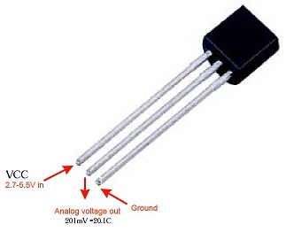
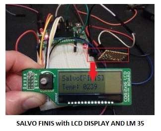
Temperature measurement is as essential application, and is one that is found in many aspects of manufacturing simply because melting temperatures, setting temperatures and operational temperatures determine if the process completes and whether the end product is useable. The type of sensor used depends on the application, and for industrial applications a type of sensor called a thermocouple is used. For the purpose of this article I am going to use a much simpler device known as the LM35. This is a very simple device that is built into the same package as a transistor, looks the same too. So they can be confused with a BC237 or similar device. While I am writing this I realized that I had written a similar article in the past. So if you are interested in some nostalgia, here is the link Temperature Display Project. This time around I am applying the same code to the Salvo [FINIS] using the PIC16F1827. This device is one that I have been using in quite a number of postings and is supplied as an alternative device to the PIC16F628 in the options from Tindie. The PIC16F628 however does not have A2D conversion, instead it has analogue comparators.
Note: This project is compatible with the PIC16F1847 as well,
Just to recap on the LM35. The LM35 converts temperature to an output voltage equivalent to 10mV / C. This level of resolution is ideal for general temperature display for example.
So below is the code, that will make the project work:
// LCD module connections
sbit LCD_RS at RA0_bit; sbit LCD_EN at RA1_bit; // sbit LCD_EN at RB3_bit; sbit LCD_D4 at RB4_bit; sbit LCD_D5 at RB5_bit; sbit LCD_D6 at RB6_bit; sbit LCD_D7 at RB7_bit;
sbit LCD_RS_Direction at TRISA0_bit; sbit LCD_EN_Direction at TRISA1_bit; // sbit LCD_EN_Direction at TRISB3_bit; sbit LCD_D4_Direction at TRISB4_bit; sbit LCD_D5_Direction at TRISB5_bit; sbit LCD_D6_Direction at TRISB6_bit; sbit LCD_D7_Direction at TRISB7_bit;
char LCDTXT[] = “Salvo[FINIS]”; char LCDMSG[] = “Data”; char uart_rd; unsigned short new_DC, current_DC; long ADC_Value = 0; unsigned int adc_rd; unsigned char ch;
Delay_ms(20); } void IOConfig() { // Disable Analog
ANSELA = 0x08; ANSELB = 0x0;
// Ports
TRISB = 0xF8; TRISA = 0x10;
// PIC16F1827 has two capture compare modules and both need to be disabled
CCP1CON = 0x0; CCP2CON = 0x0;
INTCON = 0; // disable all interrupts
CPSCON0=0;
ADCON0 = 0x10;
CM1CON0 = 0x0;
}
void LCDConfig() { Lcd_Init(); // Initialize LCD
Lcd_Cmd(_LCD_CLEAR); // Clear display Lcd_Cmd(_LCD_CURSOR_OFF); // Cursor off Lcd_Out(1,1,LCDTXT); // Write text in first row }
void main() {
IOConfig();
LCDConfig();
while(1) {
LED(); // Test display signal
TempDisplay(); } }
Step 3: Technical Details Wrap Up . . .
The more technical details: I have set the A2D input on channel four (4), but this can be moved to any of the other inputs. To change the analogue settings by changing the following the settings. The register ANSELA and ADCON0 registers, need to be changed to configure the correct CH (channel). Bear in mind that only one analogue input can be used at a time and a settling period is required if or when the channel is changed – the value is the same for both registers. In the next article, we will use the temperature display to create a thermostat of sorts which will be used to control a fan for cooling.
Overview of 1-Wire Technology and Its Use By: Bernhard Linke, Principal Member Technical Staff Jun 19, 2008
Abstract:This article provides a general overview of the 1-Wire® technology, its communication concept and, as a benefit of the low pin count, unusual package options. The main section discusses 1-Wire devices by their feature set and explains the typical applications. The article ends with practical information on how to evaluate 1-Wire devices, explains device customization options, and references resources that assist customers in integrating 1-Wire technology in their systems.
What Is 1-Wire Technology?
The basis of 1-Wire® technology is a serial protocol using a single data line plus ground reference for communication. A 1-Wire master initiates and controls the communication with one or more 1-Wire slave devices on the 1-Wire bus (Figure 1). Each 1-Wire slave device has a unique, unalterable, factory-programmed, 64-bit ID (identification number), which serves as device address on the 1-Wire bus. The 8-bit family code, a subset of the 64-bit ID, identifies the device type and functionality. Typically, 1-Wire slave devices operate over the voltage range of 2.8V (min) to 5.25V (max). Most 1-Wire devices have no pin for power supply; they take their energy from the 1-Wire bus (parasitic supply).
What Is Special About 1-Wire?
1-Wire is the only voltage-based digital system that works with two contacts, data and ground, for half-duplex bidirectional communication. In contrast to other serial communication systems such as I²C or SPI, 1-Wire devices are designed for use in a contact environment. Either disconnecting from the 1-Wire bus or a loss of contact puts the 1-Wire slaves into a defined reset state. When the voltage returns, the slaves wake up and signal their presence. With only one contact to protect, the built-in ESD protection of 1-Wire devices is extremely high. With two contacts, 1-Wire devices are the most economical way to add electronic functionality to nonelectronic objects for identification, authentication, and delivery of calibration data or manufacturing information.
Real-Time Clock (RTC) Counts Seconds, Minutes, Hours, Date of the Month, Month, Day of the week, and Year with Leap-Year Compensation Valid Up to 2100 56-Byte, Battery-Backed, General-Purpose RAM with Unlimited Writes I²C Serial Interface Programmable Square-Wave Output Signal Automatic Power-Fail Detect and Switch Circuitry Consumes Less than 500nA in Battery-Backup Mode with Oscillator Running Optional Industrial Temperature Range: -40°C to +85°C Available in 8-Pin Plastic DIP or SO Underwriters Laboratories (UL) Recognized
SEL/EXIT [selection or Exit ] Up [increment ]Down [Decrement]Set [Update the last change]
step 1: wait for the time display [ switches function disabled at time display mode ]
step 2: step 2.a Press the SEL/EXIT switch hour option selected [Up and Down button for hour ] step 2.b Press again the SEL/EXIT switch minute option selected [Up and Down button for minute ] step 2.c Press again the SEL/EXIT switch AM/PM option selected [Up and Down button for AM/PM selection ]
step 2.d Press again the SEL/EXIT switch it cancel the change and exit from updating mode if you want to save the change don’t press the SEL/EXIT button
step 3: SET Button update the last change
Step 8: Working Video
Step 9: Hex File Download
hex file rtc_temp_clock.hex
crystal 20 MHz | watch dog timer off | code protection off
The Incubator Temperature Regulator is made on a breadboard to demonstrate how to program and set the temperature of the regulator. It uses an LM35 temperature sensor, a serial LCD made with a PIC16F628A microcontroller and an Arduino Nano. The low & high setpoint is configurable to maintain the temperature range. An LED is used to represent the function of the heater. When the temperature is below the low setpoint, the LED comes “ON”. It goes “OFF’ when the temperature rises above the high setpoint.
Supplies
1. One Arduino Nano with USB Cable
2. One PIC16F628A
3. LM35 Temperature Sensor
4. One Liquid Crystal Display (LCD)
5. Four 10 Kilo-Ohms Resistors
6. One 330 Ohms Resistor
7. One 10 Kilo-Ohms Reisitor
8. Three Push-button Switches
9. One Big Breadboard
10. Three Mini-Breadboard
Step 1: Build a Serial LCD With PIC16F628A Microcontroller and Connect to the Arduino Nano
A serial LCD by Jason Jacob on LDmicro Github page (https://github.com/LDmicro/LDmicro/wiki/Stopwatch3-over-serial-LCD-based-on-HD44780-controller) was built on a breadboard. The MAX232 circuit, the transistor, and the push-button switches were removed from Jason’s serial LCD to give the stripped-down version above. Download and unzip the files. Upload the .hex file into the PIC16F628A microcontroller with the PICkit-3 programmer as demonstrated in tutorial 5. Pin 7 of the PIC16F628A should be connected to pin TX of the Arduino Nano circuit. The three push-button switches are used to adjust the low and high setpoints of the controller.
Step 2: Program the Arduino Nano With a LDmicro
See link to the LDmicro program. The code is compiled for Arduino Sketch in LDmicro. Then the Arduino IDE is used to upload the sketch to the nano.
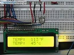
Observe that the displayed home page shows the temperature reading in both Celsius and Fahrenheit. Pressing the menu button once displays the low setpoint menu for the adjustment of the low setpoint. A second press of the Menu button displays the high setpoint menu for its adjustment. When the temperature goes below the low setpoint, the LED which represents the heater comes ON. It goes OFF when the temperature is higher than the high setpoint.
The echolocating bat is a wonderful animal that is unique in so many different ways: it is the only truly flying mammal, it can use air-coupled sonar to navigate in complete darkness while flying, it can allow its body temperature to drop to as low as 1degC (torpor) to save energy, and it has adapted to a huge range of climates and food sources (e.g., fruits, crawling and flying insects, nectar, fish, blood, etc). That’s nice, but why would a neuroscientist or engineer specifically study bats?
From a computational neuroscience perspective, bats are remarkable because of the very short timescale on which they operate. The barrage of returning sonar echoes from a bat’s near-environment lasts approximately 30 milliseconds following a sonar emission with the echo from a specific target lasting, at most, a few milliseconds. At this timescale, a particular neuron has the opportunity to fire only one or two spikes to represent the echo. Unlike the “traditional” view of cortical processing where many spikes are integrated over time to compute an average rate, the bat must rely on populations of neurons that respond transiently but selectively to different objects in the environment. In these neural circuits, the details of spike timing, synaptic dynamics, and neuron biophysics become extremely important. Flying at speeds anywhere from 1m/s to 6 m/s, a bat’s sensory world jumps from pulse to pulse as it flies through the world. Sensory prediction is therefore likely to be very important in this animal. In spite of all this behavioral specialization, the bat brain is organized like most other mammalian brains suggesting that echolocation arises from only small modifications of the typical mammalian auditory system. From an engineering standpoint, biosonar systems (e.g. bats and dolphins) have inspired the design of very sophisticated sonar and radar systems that can map distant surfaces and track targets with great precision. Even with powerful mathematical tools and decades of experience, however, our best systems still do not rival the perceptual capabilities of dolphins. Many bats demonstrate incredible aerial agility, flying in complete darkness through branches and caves while hunting evasive insects. These animals perform such tasks in real-time with a total power consumption (including flight) measured in Watts, not hundreds of Watts. In addition to the ability to navigate in complete darkness by echolocation, both bats and dolphins live in very social environments using echolocation in group situations without any obvious problems with interference. All of these capabilities are highly desired by current military programs developing unmanned-aerial vehicles (UAV) especially since many of the target environments are in places where Global Positioning System (GPS) signals are unavailable and obstacle locations are not mapped.
Goal: Our goal is to construct a flying bat-sized creature that uses ultrasonic echolocation to both navigate and scrutinize its environment sufficiently to distinguish between obstacles and “insects”. The bat’s sensory and motor system will be constructed from neural models and implemented using “neuromorphic” VLSI techniques. Our intention is two-fold: 1) to test these neural algorithms in a real-time, closed-loop behavioral situation, and 2) to develop useful sonar sensors for use in miniature aircraft systems.
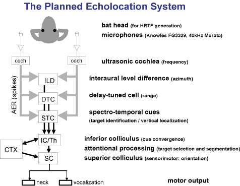
The Bat Head
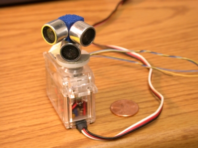
We are working with two different hardware systems: a physically-larger single-frequency sonar system (“narrowband”) and a tiny broadband system. The narrowband system is being used to rapidly test concepts following initial software tests. Photos of these two systems are found below:
In the photo to the left, is our narrowband sonar system that operates only on a frequency of 40 kHz. The fixed arrangement of the microphones was chosen to produce a difference in echo amplitude with azimuthal direction. The current system roughly extracts direction and range and is capable of servoing the head (which is mounted on an model airplane servo) to track moving targets in real-time.
On the right, we have a photo of our broadband system using a baked polymer clay bat head with a tiny Knowles (FG3329) microphone soldered to the end of a group of wires. This system has two broadband ultrasonic (and audio) microphones that will feed our silicon cochleae chips.
Both of these physical heads produce intensity difference cues at each microphone that allows the system to determine the angle of the arriving echo.
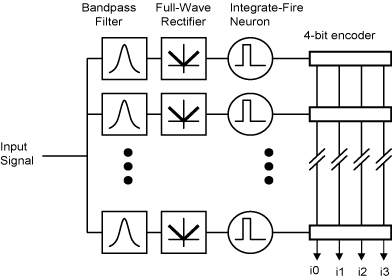
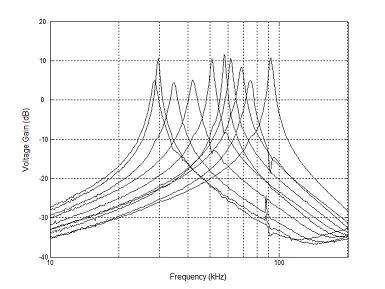
An Ultrasonic Cochlea
Echolocating bats specialize in high-frequency hearing using echolocation sounds that typically range in frequency from 20 kHz to 100 kHz. While some bats are specialized for specific frequencies with cochlear filtering at extremely high Q10dB values, we are studying bats that use a broadband vocalization and are ultrasonic frequency generalists (e.g., Myotis lucifugus) with Q10dB values in the range of 10 to 30. Good frequency resolution is important for vertical localization, discriminating close objects, as well as for prey discrimination.
To support our ongoing work in modeling bat echolocation, a binaural, ultrasonic cochlea-like filter bank has been designed with moderate quality (Q) factor (as high as 65) with spiking neurons that are driven by the filter outputs. The neuron addresses are reported off chip at the time of the spike in an unarbitrated fashion and in current-mode to reduce the amount of capacitively-coupled feedback into the filters. This chip was fabricated in a commercially-available 0.5 um CMOS process and consumes 0.425 milliwatts at 5 volts.
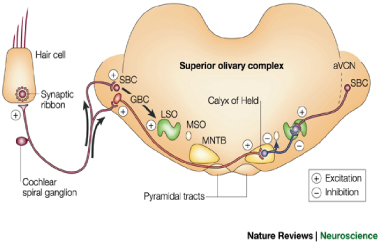
Modeling the lateral superior olive (LSO), dorsal nucleus of the lateral lemniscus (DNLL), and the inferior colliculus (IC)
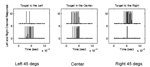
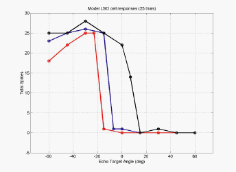
When echoes arrive from different directions, the number of spikes generated in the auditory nerve and the cochlear nucleus varies with the intensity at each ear. Using this information, the first binaural nucleus in the mammalian auditory system, the lateral superior olive (or LSO) becomes selective to the direction of arrival. These cells are excited by the intensity from one ear and inhibited by the intensity from the other ear.
The binaural LSO response and the monaural response from the cochlear nucleus is projected to the inferior colliculus (IC) via the doral nucleus of the lateral lemniscus (or DNLL), resulting in very similar responses in both DNLL and IC. With similar responses in the LSO as in the IC, one can ask the question, “what kind of computation is going on here?” In the figure to the left is a set of tuning curves for three LSO cells that have different synaptic weightings from the left and right ears. By comparing the responses of the population of LSO cells, each of which have different synaptic weightings, we can determine which direction an echo is arriving from.
In this work, we are working with a single frequency system (40kHz) and brief burst of ultrasonic energy. Here we have designed a VLSI circuit that mimics the spiking neurons of the LSO, DNLL, and IC to create the responses seen in the bat brainstem neurons.Our experimentation with the circuits and model seem to suggest that the extra synaptic interaction at the level of the DNLL and the IC creates an temporal interaction between individual echoes resulting from a single vocalization and even interactions between echoes from previous vocalizations.
We have built a multi-layer neuron chip that can simulate the LSO, DNLL, and the IC using spiking neurons. With this chip, we are exploring the role of long-lasting inhibition and refractory periods on how the spatial receptive fields of bat brainstem neurons change when multiple echoes are presented to the animal. This is a largely unexplored area of research and where there have been experiments, they show results that suggest that bats may need a more sophisticated signal processing system to untangle all of the interactions.
Delay-tuned Cells (Range tuning)
Information about target range has many uses for bats during both prey-capture and navigation tasks. Beyond the extraction of distance and velocity, it may be important for less obvious tasks, such as optimizing the parameters of the echolocation process. For example, as a bat approaches a target, it alters the repetition rate, duration, spectral content, and amplitude of its vocalizations. Not only is echolocation used for insect capture, it provides to the bat information about obstacles, roosts, altitude, and other flying creatures.
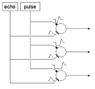
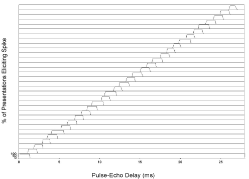
In the bat’s brainstem and midbrain exist neural circuits that are sensitive to the specific difference in time between the outgoing sonar vocalization and the returning echo. While some of the details of the neural mechanisms are known to be species-specific, a basic model of re-afference-triggered, post-inhibitory rebound timing is reasonably well supported by available data. Neurons have been found in bats that show a ‘facilitated’ response to paired sounds (a simulated vocalization and an echo) presented at particular delays. The cells’ responses to sounds presented at the appropriate delays are much greater than the sum of the responses to the individual sounds presented alone. These cells are part of a larger class of neurons called ‘combination-sensitive’ neurons, and are specifically referred to as delay-tuned cells. Delay-tuned cells are found at manylevels in the bat auditory system. They have been found in the inferior colliculus (IC), the medial geniculate body (MGB), and the auditory cortex. Disruption of cortical delay-tuned cells has been shown to impair a bat’s ability to discriminate artificial pulse-echo pair delays. It is likely that delay-tuned neurons play a role in forming the bat’s perception of range, although delay-tuned cells have also been shown to respond to the social calls of other bats.
We have designed low-power, analog VLSI circuits to mimic this mechanism and have demonstrated range-dependent outputs for use in a real-time sonar system. These circuits are being used to implement range-dependent: vocalization amplitude, vocalization rate, and closest target isolation. Power consumption is approximately 2-4 mW.
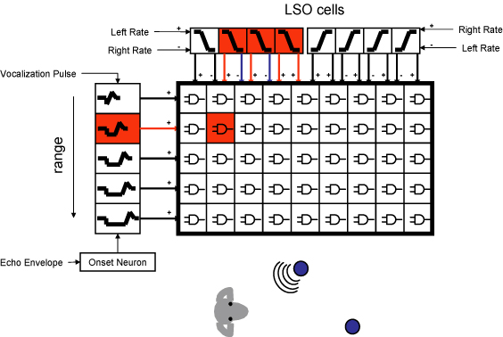
A Convergence of Range and Azimuth ( 2-D cells )
In our latest project, we have combined the work on LSO modeling which extracts information about azimuth and combined it with the range tuning cells above to create “2-D cells” which respond to a combination of range and azimuth. These circuits are coincidence detectors that respond to echoes originating from a particular direction and range.
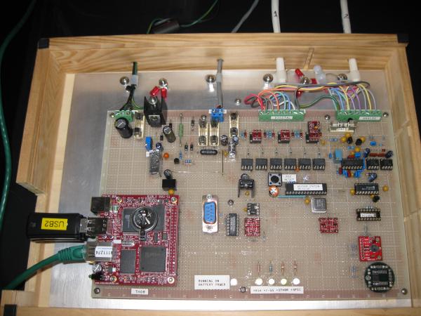
This is the Carleton Weather Station, at least the computer end of it. The data acquisition system is to the left and the web server is the Mac computer. It is located in Olin 206.
This is the Carleton Weather Station’s data acquisition system. This replaced a 1995 Mac and some daq boards. This daq system is based on a Microchip PIC18F876. It has its own battery back-up.
This is a more detailed picture of the Weather Station daq board. The board in the lower left interfaced with the PIC and the web server. It also stores the data in the thumb drives.
This shows two of the sensors located on the roof of Olin Hall. The black tube pointing down houses the humidity sensor. Inside the ‘stacked plates’ is the temperature sensor. The view is looking east, and in the distance you can see the Carleton wind turbine. (lower right center)
Located on this mast are the wind direction sensor (left side), solar radiation sensor (top center), and wind speed anemometer (right). These are located on the roof of Olin Hall.
This is the rain gauge located on the roof of Olin Hall. Inside the top is a funnel which directs water collected in the 8″ opening down to the tipping bucket.
This is what the inside of the rain gauge looks like with the funnel removed. It is kind of hard to see but the black object in the middle is the tipping bucket. When one side fills with .01″ of rain it tips to the other side and sends a pulse to the data acquisition system. The daq system counts these pulses and displays them to the nearest .01″ of rain (or melted snow in the winter).
This is a new instrument platform under development to also go on the roof of Olin Hall. The left shows two radiometer instruments on a pan-tilt platform that will track the sun. The sun will be the light source and between the sun and the sensors is the atmosphere, which will be sensed at different wavelengths to monitor its changes relating to solar absorbtion. On the platform on the top are two pyranometers, a UV radiometer, a sky temperature sensor, a full sky camera, a Photosynthetically Active Radiometer (measures the visible light spectrum used by plants), an ambient light sensor, and some special sensors. An additional boom extends out with a special barometric pressure head that compensates for wind effects, a black globe sensor that simulates how outdoor animals might experience sunlight, a microphone to ‘hear’ thunder, and a detector that can differentiate between different types of precipitation. There are also lightning detectors that work like AM radios to detect static as well as an optical sensor that can detect the flash. Also located on this structure are precipitation sensors that will signal the first drop of rain, an antenna for the Lyman Lakes buoy, and a webcam allowing users to view the inner part of campus.
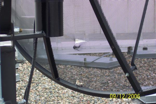
Note the two holes in the small radio telescope dish antenna located on the roof of Olin Hall. These are the result of the recent hail storm that blew thru. The top of the dish has lots of dimples in it also.
The new sidereal clock located in the 16″ dome. It gets its time from GPS and automatically dims as the dome gets darker or via wireless control.
This is the wireless control pendant that allows the operator to rotate the dome clockwise or counter-clockwise and then stop its rotation. It also has buttons to control the intensity of the sidereal clock display and an indicator to notify when the RF link’s battery is low. The pendant also has the cool abiltiy to illuminate all the buttons red when it is picked up. It does this by sensing the hand’s capacitance. This allows the operator to see the buttons while working in a darkened dome.
Located in the center of the aluminum cylinder is a Burr-Brown OPT101 photodiode/amplifier chip. It is powered by a 9 volt battery inside the box, and the signal is tapped off and output on a BNC connector. The cylinder accepts 12 mm optical filters such as narrow bandwidth interference types.
This is a handy op amp amplifier box for use in labs. It is battery powered and allows differing gains to be selected. It uses a precision op amp powered by a 9 volt battery. The negative voltage is generated by a charge pump converter. The label on the diecast aluminum box was created in Microsoft WORD and printed on a sheet of label paper and then cut to fit the top.
This is the guts of a time delay relay for a dc powered compressor. It uses an 8 pin Microchip PIC microcontroller to monitor the 24 volt dc supply. If the supply goes out of range the relay turns off. Once the power is restored at its operating specification there is a 10 minute delay before the relay is turned back on. This gives the compressor time to equalize pressures before trying to start again as might typically happen after a power outage.
This is a test project built hastily on a solder less breadboard. It uses a LM75 to read the current temperature via I2C and displays the result on three 7 segment displays. It uses a PIC16F628 with an internal 4 Mhz clock.
The program was created using JAL
Note the LM75 is a surface mount device, so I had to solder wires onto it to use it on the solderless breadboard.
Sorry for the bad quality photo. The stuff on the left is a 5V voltage regulator and not shown on the schematic below.
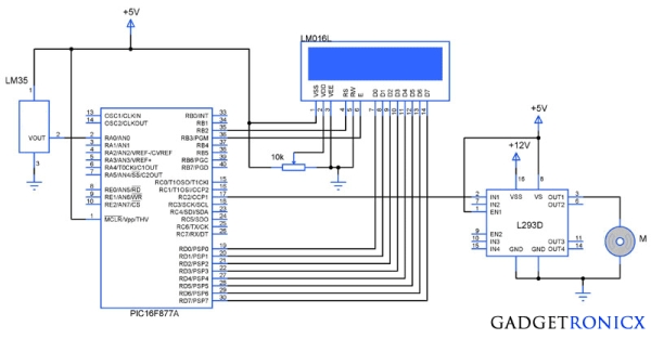
Ever needed to measure temperature and display it? This project details measuring temperature using a temperature sensor ,an ADC and a Microcontroller PIC16f84a with schematics,codes and illustrations. You can also get the following kit, although not based on the pic, which would make your life easier for your future projects.
This project was done fairly long ago, so please excuse the quality of the pictures.
Overview
The Temperature control module was a part of my Final year undergraduate project,which consisted of transmitting data wirelessly.
The module uses an inexpensive 8 bit Temperature Sensor the TMP37 from Analog Devices.
Since the data was analog and the PIC16f84 does not have an analog input,an external ADC had to be used.
Texas Instruments’ TLC549 was chosen for this.The advantage of this ADC was that it could communicate with the microcontroller serially.You may also use similar ADCs from Maxim-IC.
The LCD is a normal 16×2 display which uses the Hitachi Controller HD44780.
The module is breadboarded and not done on a PCB.Schematics are included in appropriate places below.
Capabilities of the system:
-Show Current Temperature,Set temperature and Alarm Display.
-Go into Set Mode.
-Increment/Decrement Set Point.
-Enter Set point.
The project is divided into the following subparts:
-The Analog to Digital converter TLC 549 [8 bit]
-The Temperature Sensor TMP37
-The PIC16F84 / PIC16F84a Microcontroller
-Input Buttons
-The Liquid Crystal Display [LCD]
-Temperature Control
-Codes Note:To follow this project you may need to know to program a PIC,there are some helpful links at the bottom of the page if you are not familiar with it.
The Analog to Digital converter TLC 549 [8 bit] Description : The TLC549 is an analog-to-digital converter (ADC) integrated circuit built around an 8-bit switched-capacitor successive-approximation ADC. This device is designed for serial interface with a microprocessor or peripheral.
Signals:
The TLC549 has two control lines and one data output line.
They are as follows:
–CS[bar] :: Input signal.The Chip Select signal.When low it selects/activates the chip.When high it disables the chip
–I/O clock :: Input signal.The input/output clock line is used to clock the ADC.
–Data Out :: Output signal.The data out signal clocks out bits into the PIC microcontroller.
Measurement and control of temperature and relative humidity finds applications in numerous areas. These days devices are available which have both temperature and humidity sensors with signal conditioning, ADC, calibration and communication interface all built inside them. The use of such smart sensors greatly simplify the design and reduces the overall cost. We discussed in past about Humidity and temperature measurements with Sensirion’s SHT1x/SHT7x sensors. These sensors are capable of measuring both temperature and relative humidity and provide fully calibrated digital outputs. While SHT1x/SHT7x are very accurate sensors, they are still expensive for hobbyists use. This articles discusses the DHT11 sensor which also provides calibrated digital outputs for temperature and humidity but is relatively lot cheaper than the Sensirion sensors. The DHT11 sensor uses a proprietary 1-wire protocol which we will be exploring here and implementing with the PIC16F628A microcontroller that will receive the temperature and humidity values from the sensor and display them on a 16×2 character LCD.
About DHT11 sensor
The DHT11 sensor comes in a single row 4-pin package and operates from 3.5 to 5.5V power supply. It can measure temperature from 0-50 °C with an accuracy of ±2°C and relative humidity ranging from 20-95% with an accuracy of ±5%. The sensor provides fully calibrated digital outputs for the two measurements. It has got its own proprietary 1-wire protocol, and therefore, the communication between the sensor and a microcontroller is not possible through a direct interface with any of its peripherals. The protocol must be implemented in the firmware of the MCU with precise timing required by the sensor.
The following timing diagrams describe the data transfer protocol between a MCU and the DHT11 sensor. The MCU initiates data transmission by issuing a “Start” signal. The MCU pin must be configured as output for this purpose. The MCU first pulls the data line low for at least 18 ms and then pulls it high for next 20-40 μs before it releases it. Next, the sensor responds to the MCU “Start“ signal by pulling the line low for 80 μs followed by a logic high signal that also lasts for 80 μs. Remember that the MCU pin must be configured to input after finishing the “Start“ signal. Once detecting the response signal from the sensor, the MCU should be ready to receive data from the sensor. The sensor then sends 40 bits (5 bytes) of data continuously in the data line. Note that while transmitting bytes, the sensor sends the most significant bit first.
The 40-bit data from the sensor has the following structure.
Data (40-bit) = Integer Byte of RH + Decimal Byte of RH + Integer Byte of Temp. + Decimal Byte of Temp. + Checksum Byte
For DHT11 sensor, the decimal bytes of temperature and humidity measurements are always zero. Therefore, the first and third bytes of received data actually give the numeric values of the measured relative humidity (%) and temperature (°C). The last byte is the checksum byte which is used to make sure that the data transfer has happened without any error. If all the five bytes are transferred successfully then the checksum byte must be equal to the last 8 bits of the sum of the first four bytes, i.e.,
Checksum = Last 8 bits of (Integer Byte of RH + Decimal Byte of RH + Integer Byte of Temp. + Decimal Byte of Temp.)
Now lets talk about the most important thing, which is signalling for transmitting “0″ and “1″. In order to send a bit of data, the sensor first pulls the line low for 50 μs. Then it raises the line to high for 26-28 μs if it has to send “0″, or for 70 μs if the bit to be transmitted is “1″. So it is the width of the positive pulse that carries information about 1 and 0.
At the end of the last transmitted bit, the sensor pulls the data line low for 50 μs and then releases it. The DHT11 sensor requires an external pull-up resistor to be connected between its Vcc and the data line so that under idle condition, the data line is always pulled high. After finishing the data transmission and releasing the data line, the DHT11 sensor goes to the low-power consumption mode until a new “Start” signal arrives from the MCU.
Circuit diagram
Here is the circuit diagram showing the DHT11 sensor and a HD44780-based character LCD interfaced to the PIC16F628A microcontroller. The microcontroller runs at 4.0 MHz clock using an external resonator connected between OSC1 (16) and OSC2 (15) pins. The use of 4.0 MHz clock makes the timing calculation easier as 1 machine cycle becomes 1 μs. The timing information will be used to calculate the width of the received data pulse from the sensor so that we could identify if it is carrying a 1 or 0.
It is a very simple data logger project based on PIC12F683 microcontroller. The microcontroller reads temperature values from a temperature sensor on a regular interval basis and stores them into its internal EEPROM memory. The recorded temperatures can be later transferred to a PC through serial interface. I originally published this project on electronics-lab.com last summer. I thought this could be a very good learning project for beginners, and so I am posting it here for Embedded Lab’s readers too.
Theory
The sensor used in this project is DS18B20. It is a digital temperature sensor manufactured by Dallas Semiconductor (now MAXIM) that can measure temperature ranging from -55°C to +125°C with an accuracy of ±0.5°C over the range of -10°C to +85°C. The sensor provides the measured temperature (°C) output in user-configurable 9, 10, 11, or 12-bit data corresponding to the desired resolution of 0.5, 0.25, 0.125, and 0.0625 °C. The sensor communicates with a host microcontroller over a 1-wire bus. Readers are suggested to refer the datasheet on Maxim’s website for details on this sensor. Please keep in mind that there are three versions of this sensors, namely DS1820, DS18S20, and DS18B20, and they have some architectural differences. All of them have the same pin configuration and therefore the circuit diagram would be same for all three types. However, some modification in the software may be required while the microcontroller reads the temperature data from them.
PIC12F683 has 256 bytes of internal EEPROM. Each temperature reading is stored as a byte, which means only the eight most significant bits of DS18B20 output is recorded. Therefore, the temperature resolution is decreased down to 1 °C. This temperature logger can store up to 254 temperature values (254 bytes) in its internal EEPROM. The remaining two EEPROM locations are used to store the sampling time and number of samples information. Three tact switches are used to provide user inputs for controlling the operation of the data logger.
Circuit Diagram
The PIC microcontroller uses its internal clock source operated at 4.0 MHz. The DS18B20 sensor is interfaced to GP0 pin (7) of the microcontroller. An LED connected to the GP2 pin serves as the only display in the circuit to indicate various actions of the data logger. For example, it blinks every time a sample is recorded into EEPROM. The circuit is powered with +5 V derived from a 9V battery using an LM78L05 regulator IC. The LM78L05 circuit is a very common circuit and therefore, it is not shown here.
The three tact switches provide the following functions.
Start: Starts data logging
Stop: Stops the logging procedure
Send/Reset: Transfers data to PC through serial port. However, if it is held pressed for 2 sec or more, the EEPROM locations are cleared and ready for new recordings.
Selection of sampling time
This data logger offers three options for sampling interval: 1 sec, 1min, and 10 min. The selection is made through the same three tact switches. Here is how it works. Suppose if 10 min sampling time is needed, then first turn OFF the power, hold the ‘Send/Reset’ button pressed, turn the power ON, and wait till the LED glows. Once the LED glows, release the button, and the sampling interval is set to 10 min. The new sampling time will be updated to EEPROM location 0 so that in case of power failure, the previous sampling time will be restored. Similarly, the use of ‘Start’ or ‘Stop’ button instead of the Send/Reset one sets the sampling time to 1 sec, or 1 min respectively. With 10 min sampling interval, this data logger can record temperature samples over 42 hours.
Serial Interface to PC
Transferring data to PC through serial port requires a voltage translation circuit to convert the TTL logic levels from PIC12F683 to appropriate RS232 voltage levels. A regular PNP transistor with few other passive components can do this job. The RS232 standard uses a -3 to -12 V for Logic 1 and +3 to +12 V for Logic 0. The required negative voltage is stolen from the TX pin of the RS232 port on PC’s side which is unused as there won’t be any data transfer from the PC to PIC12F683. Under idle condition the TX pin on PC’s side is held high (-12 V). The two figures below describe the operation of converting TTL levels for 1 and 0 to corresponding RS232 levels. The positive terminal of the 10 uF capacitor is grounded because its negative terminal has to deal with a more negative voltage.
Recently i won a bid for a batch of 10K thermistors. The only thing that i knew when i got them in my hand, was that those things are 10K thermistors. As far as i know, the 10K nominal resistance is at room temperature (25�C). But i had to find out if these are PTC or NTC, and also i had to draw their resistance to temperature characteristic line, otherwise they would be useless to me. So i ran some experiments with them…
A thermistor is actually a part that changes its resistance with the temperature change. There are namely 2 types of thermistors, the NTC and the PTC. The ‘T’ and ‘C’ stands for “Temperature” and “Coefficient”. The “P” stands for “Positive” and “N” for “Negative”. So, a NTC will decrease its resistance while the temperature rises, and a PTC will do the opposite.
Also, there are linear and non-linear thermistors. The old thermistors were uusually non-linear. This means that the resistance does not change linear to the temperature. That was a headache for taking measurements and the labs developed very linear sensors that are widely used nowadays. Every sensor should have a temperature to resistance characteristic diagram. But what i got was only a batch of sensors and nothing more.
What i had to find out was the type of the thermistors (PTC or NTC), and the resistance to temperature change characteristic.
The experiment
For this, i will use a PIC microcontroller. I chose the 16F1937 because… i had it already mounted on a breadboard. Actually, any other PIC with analog to digital conversion capability would do just fine. Then i connected a DS1621 temperature sensor. These sensors have an outstanding measuring accuracy.
Then i used a 10K resistor to create a voltage divider with the thermistor. According to the standard specifications of thermistors, when it is in room temperature (25�C) it should have its nominal resistance, which in my case it is 10K. So, the output of the voltage divider should be 2.5 Volts. The PIC will measure this analog value. It then will get a binary 8-bit number from 0 to 255, representing this voltage.
The idea is to get as much measurements as possible for different temperatures. The more the measurements, the higher the accuracy. But this is not all. To have an overall image of the characteristic of the thermistor, i need to have a wide range of temperatures. The wider the temperature range, the better the accuracy of the characteristic. This is not easy though. I had to find a way to measure from very low temperatures (as low as 0�C) to high temperatures up to 50 �C. I do not really have device to do this, so i had to find different ways.
First of all the external ambient temperature. Today we had temperatures from 17.5�C up to about 22�C. This is a nice way to start. Then i used a thermal gun to increase gradually the temperature up to 50�C. My thermal gun has an electronic adjustment. I hang it over the circuit at about half a meter away and let it run with different setting every time. With this way, i had a batch of nice stable measurement up to 50�C.
The hardest part was the lower temperatures. the only thing available in my house that could work was the refrigerator. And this is exactly what i did. I put the circuit in the refrigerator while in operation. Every one hour i opened the door and quickly note the readings on the display. Then i slightly changed the setting of the refrigerator and repeated this process. It did work!
A digital thermometer is a good choice of project for beginners who just stepped in to the world of microcontrollers because it provides an opportunity to learn using sensors to measure the real world signals that are analog in nature. This article describes a similar project based on a PIC16F688 microcontroller and an LM35 temperature sensor. LM35 is an analog sensor that converts the surrounding temperature to a proportional analog voltage. The output from the sensor is connected to one of the ADC channel inputs of the PIC16F688 microcontroller to derive the equivalent temperature value in digital format. The computed temperature is displayed in a 16×2 character LCD, in both °C and °F scales.
Theory
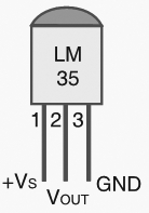
The LM35 series of temperature sensors are produced by National Semiconductor Corporation and are rated to operate over a -55 °C to 150°C temperature range. These sensors do not require any external calibration and the output voltage is proportional to the temperature. The scale factor for temperature to voltage conversion is 10 mV per °C. The LM35 series sensors come in different packages. The one I used is in a hermatic TO-46 transistor package where the metal case is connected to the negative pin (Gnd).
The measurement of negative temperatures (below 0°C) requires a negative voltage source. However, this project does not use any negative voltage source, and therefore will demonstrate the use of sensor for measuring temperatures above 0°C (up to 100°C).
The output voltage from the sensor is converted to a 10-bit digital number using the internal ADC of the PIC16F688. Since the voltage to be measured by the ADC ranges from 0 to 1.0V (that corresponds to maximum temperature range, 100 °C), the ADC requires a lower reference voltage (instead of the supply voltage Vdd = 5V) for A/D conversion in order to get better accuracy. The lower reference voltage can be provided using a Zener diode, a resistor network, or sometime just simple diodes. You can derive an approximate 1.2V reference voltage by connecting two diodes and a resistor in series across the supply voltage, as shown below. As a demonstration, I am going to use this circuit in this project. I measured the output voltage across the two diodes as 1.196 V. The resistor R I used is of 3.6K, but you can use 1K too. The important thing is to measure the voltage across the two diodes as accurate as possible.
We need do some math for A/D conversion. Our Vref is 1.196 V, and the ADC is 10-bit. So, any input voltage from 0-1.196 will be mapped to a digital number between 0-1023. The resolution of ADC is 1.196/1024 = 0.001168 V/Count. Therefore, the digital output corresponding to any input voltage Vin = Vin/0.001168. Now, lets see how to get the temperature back from this whole process of converting sensor’s output to 10-bit digital number.
Assume, the surrounding temperature is 26.4 °C. The sensor output will be 264 mV (0.264 V). The output of ADC will be 0.264/0.001168 = 226. If we reverse this process, we have 226 from ADC and we can go back and find the temperature by using the sensor scale factor (10 mV/°C),
temperature = 226 * 0.001168 (V/Count) / 0.01 (V/°C) = 26.4 °C
If you want to avoid floating point math in your program, just use,
temperature = 226 * 1168 = 263968
While displaying this, you need to put a decimal at the fourth place from the left. So the calculated temperature is 26.3968°C, which is pretty close to the actual one. The difference is caused by quantization and rounding errors. In this project, we will display temperature accurate to one decimal place, i.e., we will divide the above number by 1000 to get 263. So the temperature will be displayed as 26.3 °C.
Once you have derived the temperature back in °C, you can convert it to °F using a simple equation,
temperature in °F = 9 x temperature in °C /5 + 32
In this case, the number you got for °C is scaled by 10 (263 for 26.3), you should use
temperature in °F = 9 x temperature in °C /5 + 320
Since, the number for °C may not be exactly divisible by 5 (such as 263 is not), you can further eliminate the floating point by scaling it one more time by 10. So the new equation will be,
temperature in °F = 9 x temperature in °C x 10 /5 + 3200
or, temperature in °F = 18 x temperature in °C + 3200 = 18 x 263+3200 = 7934
79.34 °F is equivalent to 26.3 °C. In this project, it will be displayed as 79.3 °F.
Circuit Diagram
An external reference voltage to the internal ADC of PIC16F688 can be provided through RA1 I/O pin. The output from the LM35 sensor is read through RA2/AN2 ADC channel. The temperature is displayed on a 16×2 character LCD that is operating in the 4-bit mode. A 5K potentiometer is used to adjust the contrast level on the display. The detail circuit diagram is given below. Note that the PIC16F688 uses its internal clock at 4.0 MHz.
Digital thermometers are cool devices as they show temperatures in human readable formats. This digital thermometer project is based on a PIC16F688 microcontroller and a DS1820 temperature sensor, and it displays temperature on a character LCD screen in both Celsius and Fahrenheit scales. I selected PIC16F688 for this project because it is cheap (I bought one for $1.50). DS1820 is a 3-pin digital temperature sensor from Dallas semiconductors (now Maxim) which is designed to measure temperatures ranging from -55 to +125 °C in 0.5 °C increments. The firmware I have written is able to read and display the entire temperature range of DS1820. In order to test for temperature measurements below 0°C, I put the sensor inside my freezer. While trying this, don’t put the whole unit inside the freezer as LCD display unit may stop working at the freezer temperature. Similarly, bringing a soldering iron tip close to the sensor can do testing for the higher range temperature values.
About DS1820
I suggest reading my previous articles on DS1820 for getting details about this 1-wire temperature sensor. The firmware that I wrote works only for DS1820 (it may work for DS18S20 making some change in the temperature conversion time, read http://www.maxim-ic.com/datasheet/index.mvp/id/3021). It will definitely not work for DS18B20.
DS1820 converts temperature in to a 9-bit digital word, which is read by PIC16F688 as two bytes (TempH and TempL). The value of the least significant bit is 0.5°C. For positive temperature, the next eight bits after the LSB gives the integer part of the temperature. For example, 000110011 represents 25.5°C. Further, the floating-point math can be avoided during C to F conversion by using a scale factor of 10. Therefore, 25.5°C (scaled 255) is converted to F as,
However, the negative temperatures are stored in 2’s complement form. So the most significant bit of the 2-byte temperature reading from DS1820 is 1 if the temperature is below 0°C. The firmware takes care of all negative temperature readings (in both C and F scales). The computed temperature is displayed on LCD as a 5-digit string array, xxx.x (e.g., 24.5, 101.0, -12.5, etc).
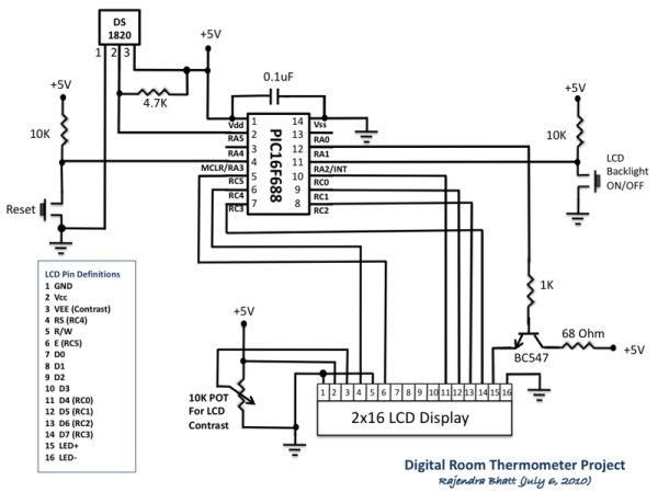
Circuit Diagram
The circuit diagram of this project is shown below. DS1820 sensor output is read by PIC16F688 through RA5 port. The computed temperature is converted to a string and sent to the LCD to display. The LCD is operating in 4-bit mode, and ports RC0-RC3 serves D4-D7 data pins of the LCD. The Register Select (RS) and Enable (E) signals for LCD are provided through ports RC4 and RC5. The Read/Write pin of the LCD is permanently grounded, as there is no data read from the LCD in this project. The contrast adjustment of LCD is done with the 10K potentiometer shown in the circuit diagram.
You might have come across several applications where we need to control a specific device based on analog parameter. This Embedded system works in a similar concept where we are about to control the speed of a DC motor using based on the external temperature. The rise in temperature will result in increase in speed of the motor and vice versa. These type of Temperature controlled fan systems can generally be used to maintain temperature of a room or object automatically.
DESIGN OF TEMPERATURE CONTROLLED FAN SYSTEM:
The temperature is measured by means of a temperature sensor LM35.
The output voltage of the sensor is fed to the A/D channel of the Microcontroller.
Based on the sensed temperature the speed of the motor is controlled using PWM .
Several temperature ranges was set in the code to vary the motor speed based on the level of temperature sensed.
The speed of the motor is controlled by using PWM.
Lm 35 is used to sense the external temperature which is capable of sensing temperature ranges from -55 to 150 C. The output voltage is proportional to the temperature hence there is no need of trimmers to calibrate the reading. The output voltage of this sensor varies by 10mv per degree change in temperature.
CALIBRATION:
We are using a 10 bit ADC and Vcc as Vref to the ADC module of the Controller. So in order to determine the step size we have to divide the Vref by our resolution that is 2^10 ( 1024 ).
Step Size = 5 / 1024 = 4.83mV
We obtain a change of 10mV with each rise or fall in temperature from the sensor. And value in the ADC register will alter by two steps with each degree change in the sensor since two increments of step size i.e 4.833mV * 2 = 9.96mV which is approximately equal to 10mV. So in order to obtain the original value we have to divide the contents in the ADC register by 2
CODE:
This code was built using CCS compiler for PIC Microcontrollers.
The above code uses built in functions in the CCS compiler to use the A/D and PWM feature in the Microcontroller. The received analog value is calibrated to display the temperature in the LCD. The “real_value” int value is converted to character using “sprintf” in order to display the temperature values.
The temperature ranges and duty cycle of the PWM is given using the subroutine “.motor”. So the microcontroller runs a check on the temperature every time and alters the speed of the motor based on it.
An on-line monitoring system of temperature of conductors and fittings based on GSM SMS and Zigbee is produced in this project, by which the temperature of conductors and fittings can be monitored in real-time and some accidents caused by the increased temperature can be avoided. The principle and the feature of GSM SMS and Zigbee communication are analyzed. The construction of this system is outlined, and the force modal of calculating the variety of the sag due to the increased temperature of conductors is built. The Zigbee communication module is produced based on RF4CE standard. Finally, the software and hardware design of the online temperature monitoring unit of conductors and fittings are outlined.
Project Description
With fast development of economy in India, the demand of electricity is higher and higher, and the problem between lag of construction of network and inadequacy of transmission capacity becomes increasingly prominent, which exacerbates the unharmonious contradictions of development between power grids and power generation structure. Some provinces and cities have begun to take power limited policies to alleviate contradiction of the current electricity supply-demand, how to resolve this problem has become imperative responsibility for many power workers. Recently, in order to prevent overloading of transmission lines, domestic power system usually adopts the static, conservative transmission capacity value in design, which is a conservative static value based on the severest weather conditions.
However, such severe weather conditions rarely occurred, and it has resulted in the inefficient use of potential transmission capacities in most time. In the situation of “east-west power transmission, south-north power transaction, nationwide electricity interconnection”, long-distance, large-capacity and high-voltage transmission lines will be more and more. By 2010, the transmission capacity of some main lines of 500 kV will reach or exceed 1 GW. By 2020, the transmission capacity for most lines of 500 kV will reach 1 ~ 1. 5GW. Some normal current for heavy short lines will reach 2 GW, which will be near 3 GW in accidents. Now, according to the traditional technology, the transmission capacity can be increased only by adding transmission lines. However, it is becoming more and more difficult to build new transmission lines with the transmission lines increased.
From the perspective of sustainable development and environmental protection, we should pay more attention from power grids expansion to increase the potential transmission capacity of available transmission lines, and enhance the transmission capacity of power grids, so as to resolve the problems between high requirement of electricity and difficulty of new transmission line. In March 2005, the State Grids held a particular meeting about improving the transmission capacity of power grids in Beijing, the meeting pointed out that at the same time of building main electrified wire netting of super high voltage, we need actively and fully tap the potential of existing capacity. At present, some areas adopt the allowable temperature value of 70 to 80 or even 90. Properly increasing the allowable temperature of existing conductors can increase stable carrying capacity of transmission lines, thereby the normal transmission capacity is improved. The method is a breakthrough of current technical regulations, the impact caused by improving conductor temperature on conductors, the mechanical strength and the lifespan of matched fittings, the increase in sag and so on should be studied. In addition, if the conductor temperature and the sag can be real-timely monitored, the dynamic regulation of the transmission capacity, such as day and night, cloudy and sunny, summer and winter under the different environmental conditions can be realized to improve the transmission capacity. In order to meet these demands, an on-line monitoring system of temperature of conductors and fittings based on GSMSMS and Zigbee is studied and developed in this paper.
Introduction to GSMSMS, ZigBee and LM35
A. GSMSMS GSM (Global System Mobile Communications) is a global digital mobile communication system, whose coverage is the most widely, phone owners is the largest, and reliability is very high. SMS (Short Message Service) is a kind of short message transmitted. In fact, the information transmission is achieved by receiving and sending text message in the businesses center between mobile phones and other short message carriers, and the businesses center is an independent operating system of GSM network whose main function is submitting, storing, and transferring short message. SMS is a special and important service as well as calling for users by GSM system. In this project, a self-designed industrial GSM module is selected to finish the transmission and the decoding of the monitoring data through AT command and coding of short message PDU (Protocol Data Unit).
B. ZigBee
ZigBee wireless network technology is a new standard launched and made by ZigBee Alliance. The alliance, founded in August 2001, is a fast-growing and non-profit organization, and it aims is to provide consumers with more flexible and easier electronic products. The second half of 2002, four large corporations including the British company Invensys, Mitsubishi Electric Corporation, Motorola and the Dutch giant Philips Semiconductor Corporation jointed together to announce that they would join the “ZigBee Alliance” to invent the next-generation wireless communication standards named “ZigBee”, which became a significant milestone in the development process. In October 2004, the ZigBee Alliance announced a version 1.0 of ZigBee protocol, and in December 2005 version 1.1. ZigBee uses free frequency bands of 2.4 GHz and 900 MHz, and its transmission rate is 20 kbps to 250 kbps. In this paper, the perfect chip cc2430 is selected to design the wireless hardware platforms of ZigBee, a standard ZigBee wireless network module is produced, and a reduced version of ZigBee wireless network protocol is programmed. The Zigbee module and protocol have been successfully applied to power system, medical and some other fields.
ZigBee is the set of specs built around the IEEE 802.15.4 wireless protocol. The IEEE is the Institute of Electrical and Electronics Engineers. They are a non-profit organization dedicated to furthering technology involving electronics and electronic devices. The 802 group is the section of the IEEE involved in Information technology—Telecommunications and information exchange between systems—Local and metropolitan area networks including mid-sized networks. Group 15.4 deals specifically with wireless networking (Wireless Medium Access Control (MAC) and Physical Layer (PHY) Specifications for Low-Rate Wireless Personal Area Networks (WPANs) technologies.
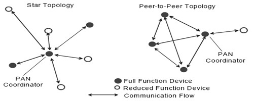
Network Topologies
Depending on the application requirements, an IEEE 802.15.4 LR-WPAN may operate in either of two topologies: the star topology or the peer-to-peer topology. Both are shown in Figure. In the star topology the communication is established between devices and a single central controller, called the PAN coordinator.
Temperature Measurement
Temperature can be measured via a diverse array of sensors. All of them infer temperature by sensing some change in a physical characteristic. Six types with which the engineer is likely to come into contact are: thermocouples, resistive temperature devices (RTDs and thermostats), infrared radiators, bimetallic devices, liquid expansion devices, and change-of-state devices.
The Overall Structure of Online
Monitoring System
The online monitoring system of temperature of conductors and fittings based on GSMSMS and Zigbee is mainly composed of the municipal monitoring center, the communication unit, the temperature monitoring unit and the expert software, the topology of system is shown in Fig.1. The communication unit is installed on the tower with both GSM and Zigbee communication modules, and the temperature monitoring unit on the corresponding conductors with the same potential.
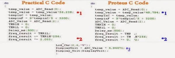
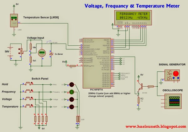
Voltage, Temperature and Frequency can switching to each others using push buttons.
Voltage Meter can measure DC voltage between 0v to 50v.
Frequency Meter can measure frequency up to 65KHz.
Temperature Meter can use between 00C to 1500C.
Every functions can paused using push button.
Instructions…
Voltage meter –
Volt meter can measure dc voltages up to 50v. 5V is the maximum voltage can handle PIC microcontroller, as it is voltage divider (10K,1.1K) use for convert 50V to 5V . 5v zener diode use for safety of PIC microcontroller analog input pin.
Temperature meter –
Temperature meter can use between 00C to 1500C. But LM35 sensor can use between -550C to 1500C. Sensor’s resistant is changing opposite to temperature, as it is maximum temperature gives maximum voltage output(5v) and minimum temperature gives minimum voltage output(0v).
Frequency meter –
Theoretically, frequency meter can use up to 65KHz, that is because this circuit made by using Timer 1(16bit) of PIC microcontroller.
Timer 0 can only measure up to 256Hz, that is because timer 0 is 8 bit timer. Transistor part is use for safety of microcontroller from amplitude of wave signal. This circuit can apply 12v amplitude or more changing transistor base resistor value(4.7K). I tested it, using 12v amplitude square wave signal.
Troubleshooting…
If you have problem about accuracy of voltmeter, temperature meter and frequency meter, you can change values (*1,*2,*3)
Hi friends, today we will see how to make temperature indicator using PIC microcontroller. The basic aim of this project is make you familiar with PIC microcontroller. It also explains how LM35 and 7 segment displays can be interfaced with PIC microcontroller.
Components required:
Following is a list of components required for temperature indicator using PIC microcontroller – mini project:
Following figure shows circuit diagram of temperature indicator using PIC microcontroller.
Theory:
In this mini project we have used PIC microcontroller and a four digit seven segment display is interfaced with it. For sensing the surrounding temperature we have used a temperature sensing IC i.e. LM35. You can use a voltmeter to crosscheck whether the indictor giving correct output or not. The output of the temperature in terms of volts will be in the range of mV.
Working of LM35:
LM35 is an integrated temperature sensor. It produces output voltage proportional to the temperature. The advantage of using LM35 is that it does not require any external calibration technique and it has accuracy of ±0.4 degree Celsius at room temperature. It draws only 60µA from supply and possesses low self heating. Thus the chances of error get minimized.
Introduction Measurement and control systems play a crucial role in the field of biosystems engineering. In the digital era, these systems are pervasive and essential, serving the dual purpose of gathering data (measurement) and automating processes (control). As an example, consider weather stations that measure variables like temperature, precipitation, wind speed, and other environmental factors. …
The concluding assignment in ECE 4760 involves the creation of a respiratory monitor tailored for use in resource-constrained settings. This device determines a patient’s respiration rate by identifying temperature fluctuations as the patient breathes through a mask. Notable attributes of this device encompass an alarm mechanism activated by a piezoelectric speaker, which triggers when the …
ABSTRACT In the industrial setting, accurately measuring the temperature of boiled water is a crucial undertaking. This paper presents the design and implementation of a temperature measurement system for boiled water utilizing a PIC microcontroller, specifically the PIC 18F452, and a temperature sensor from National Semiconductors, the LM35. The designed system is employed to gauge …